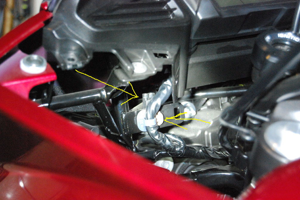
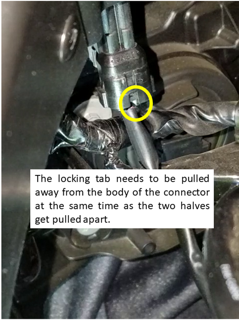
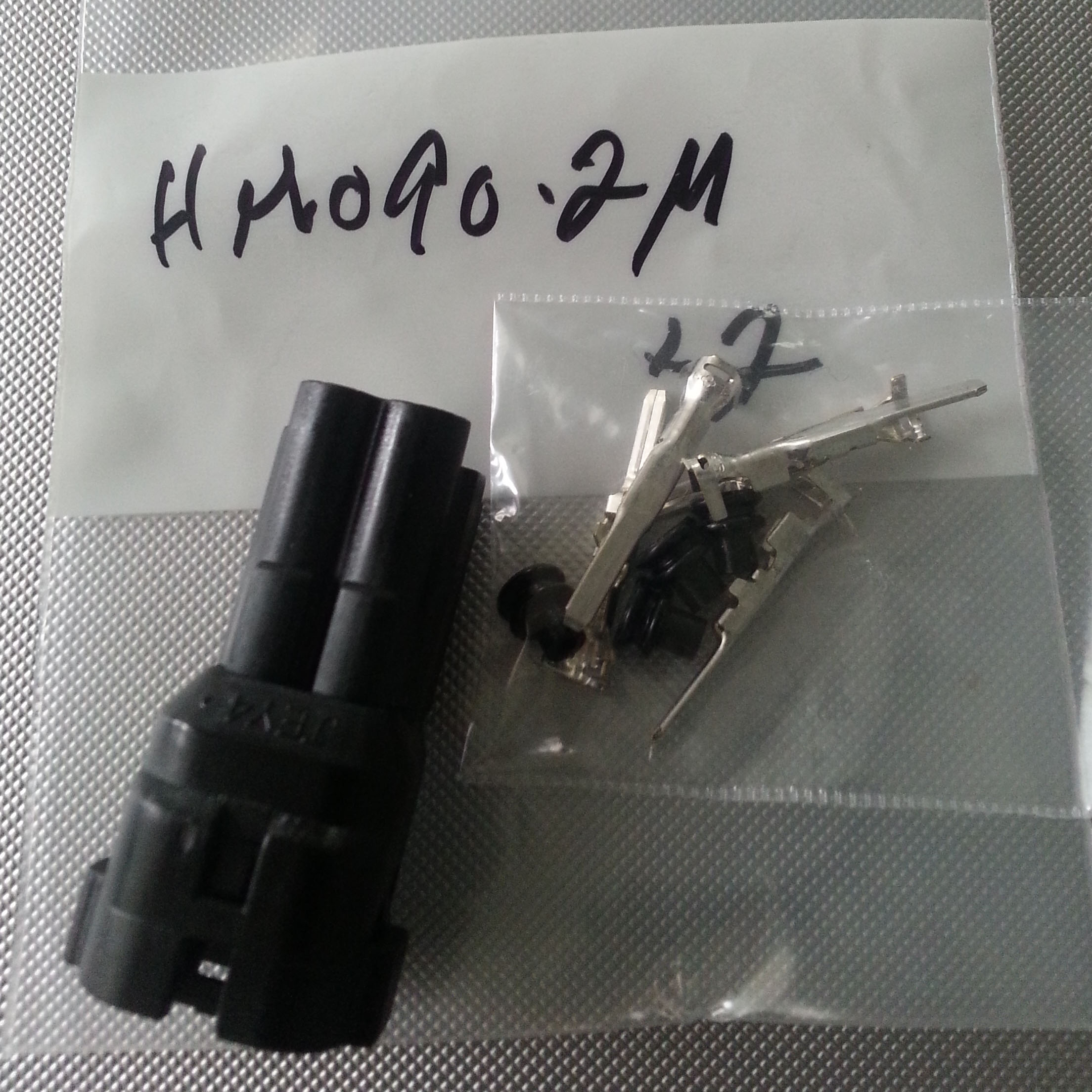
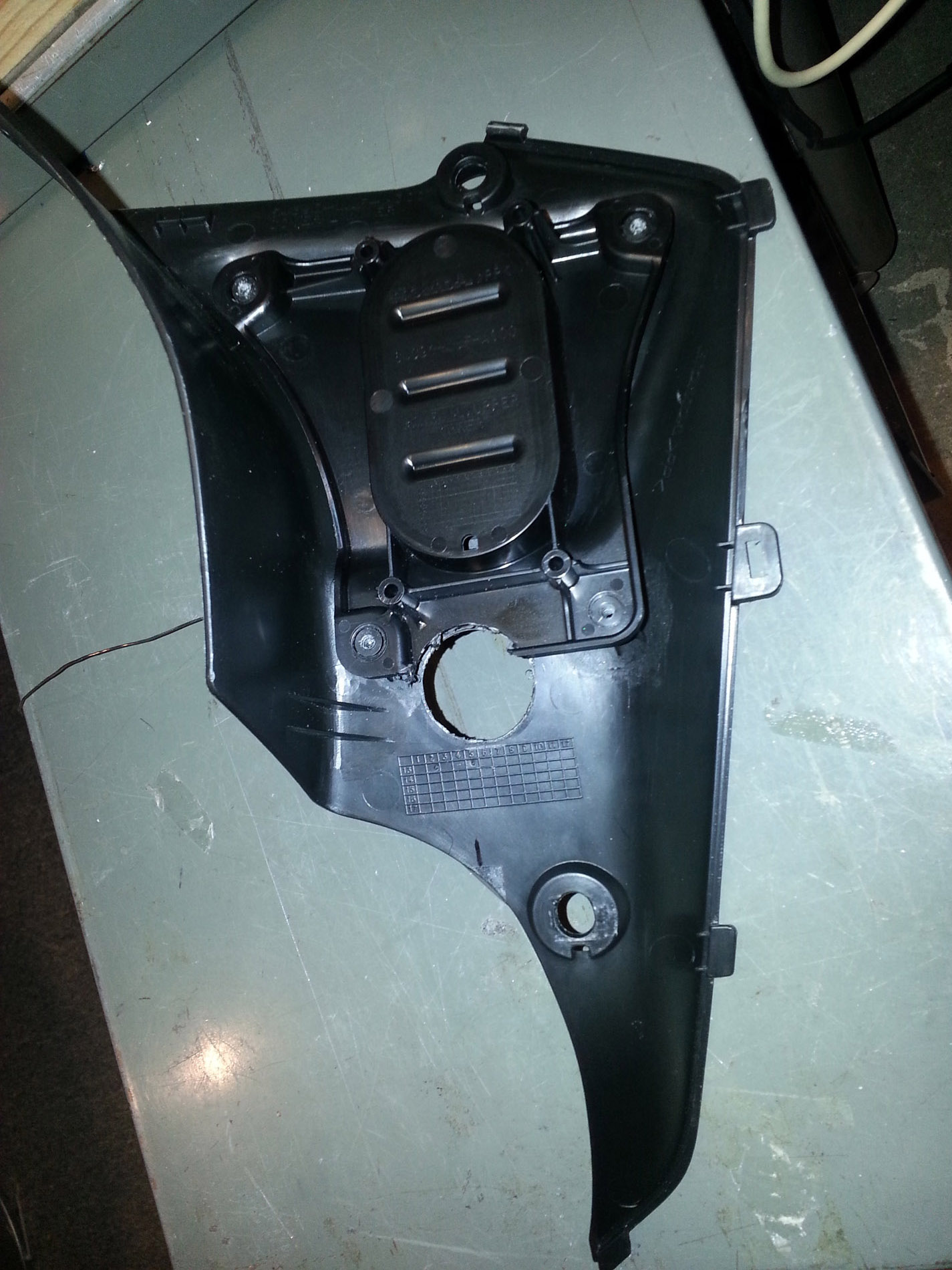
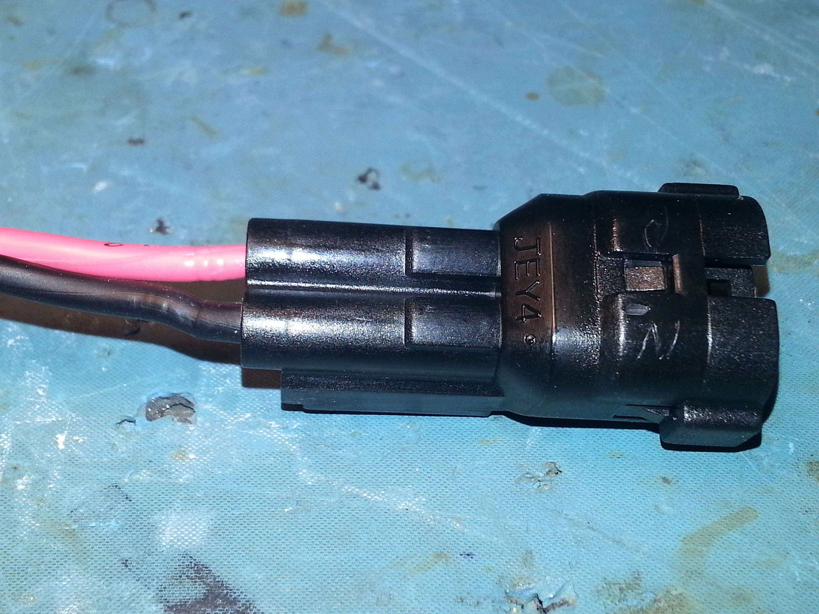
| The connector for the heated grips can be accessed by removing the left "speaker" panel and looking almost horizontally at the rear side of the fairing. It's marked by the left arrow. The harness has a dummy connector installed to keep the contacts clean. Removing the connector from the bike is as easy as pinching the two tabs in the right side of the picture. The whole thing will pop free. The dummy is removed by pulling up on the locking tab. It will pop when it comes free. The mate to the harness end connector is a Sumitomo 6187-2801 and is available in single piece quantity from cycleterminal.com The part number is HM090-2. The black male connector is the only thing that's needed. The cycleterminal HM090 page is setup to show all of the different versions of the HM090 connector. The TWO PIN version is about halfway down the page. |
|
|
|
|
|
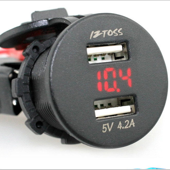
| The aux power is only present when the bike is running. The connector provides 12vdc to a dual USB socket that I mounted below the left fairing "speaker" grill. I found a USB power jack with an integrated voltmeter! That's what cinched it for me. The cable I'm making will have a micro atx fuse inline. The dual usb gizmo is from where else but Ebay! There are too many different versions out there to really matter. The hole size in the plastic is all about the same. |
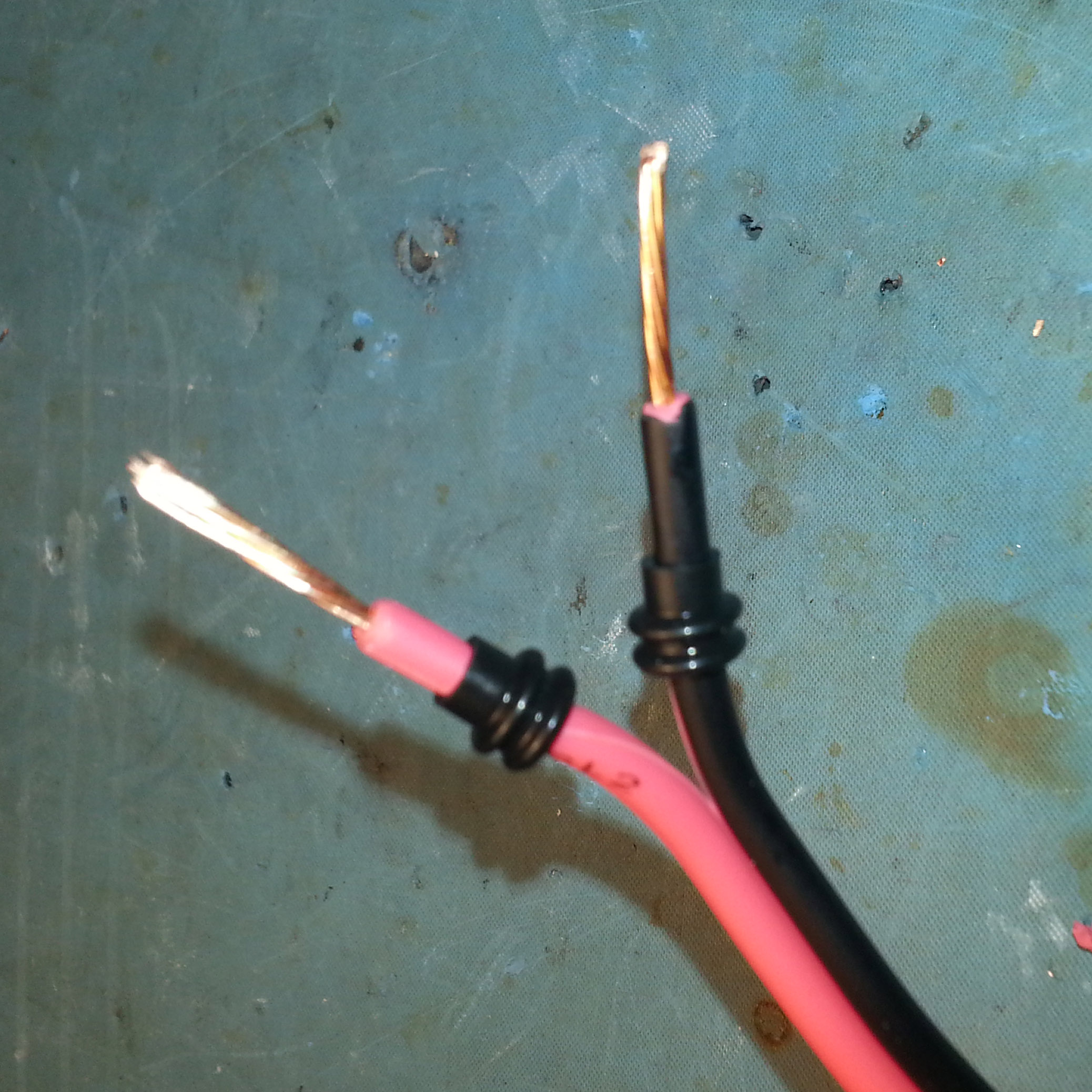
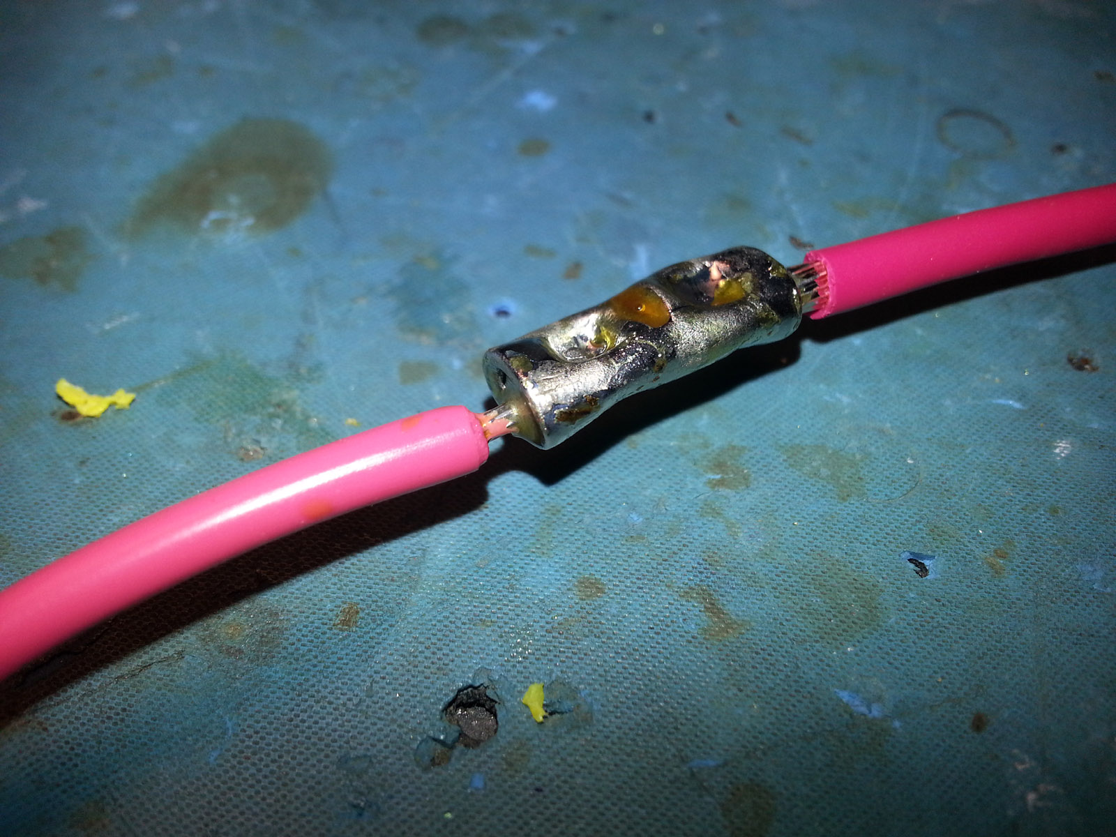
So now its time to make the actual connector. Pictures are worth more than words so here goes.... One small note.... Don't use wire that has a jacket that melts or swells when the wire is soldered. It can be a PITA to get the seals into position if it does. I stripped a little less than a half of an inch of insulation. That gave me just enough room to get the seal "crimped" just right. I don't own the correct crimper so I used a 9" pair of needle nose pliers to cinch the connector onto the tinned wire. |
|
|

Leaving a little bare wire behind the pins allows the seal to get crimped easily. |
|
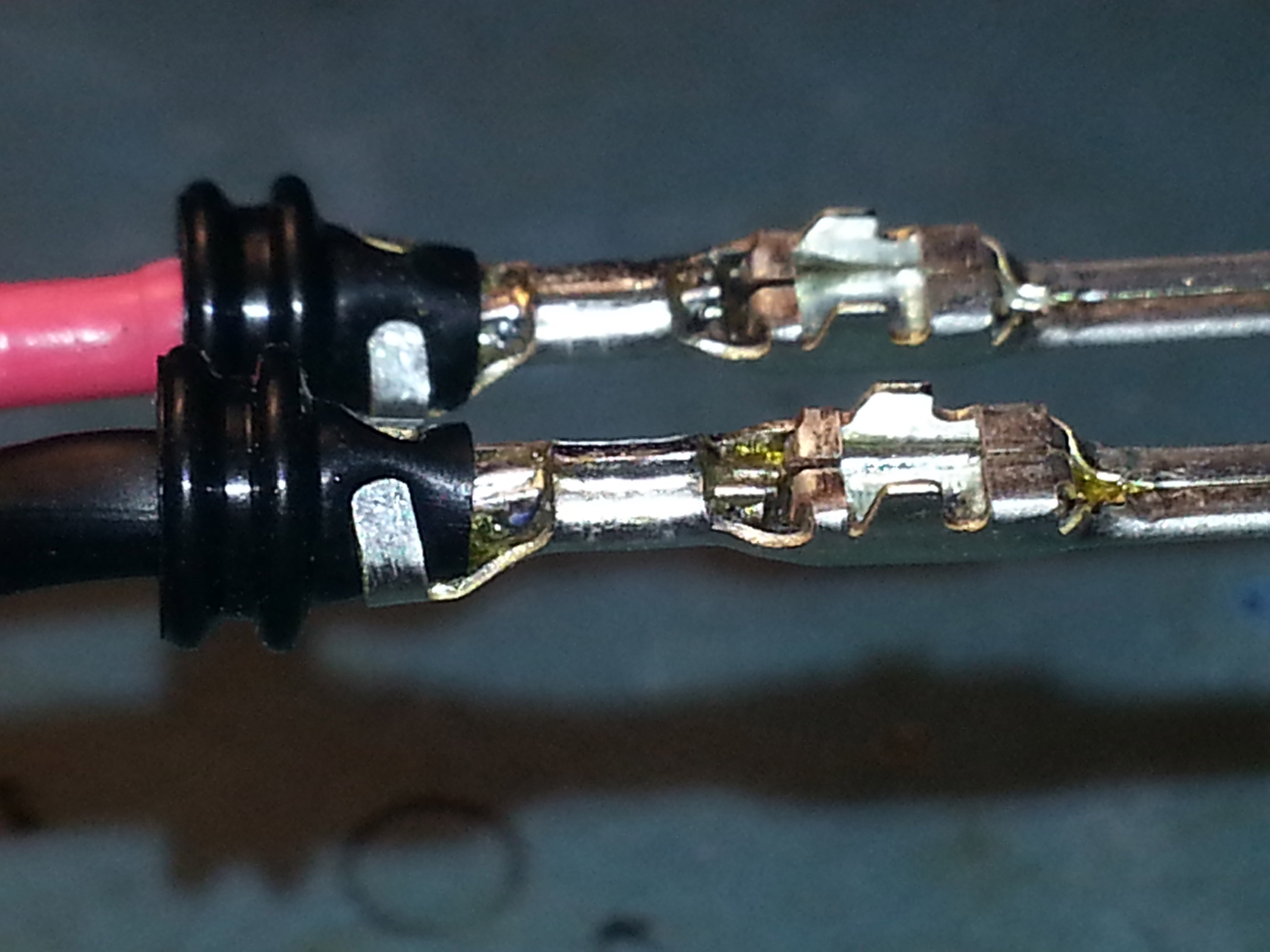
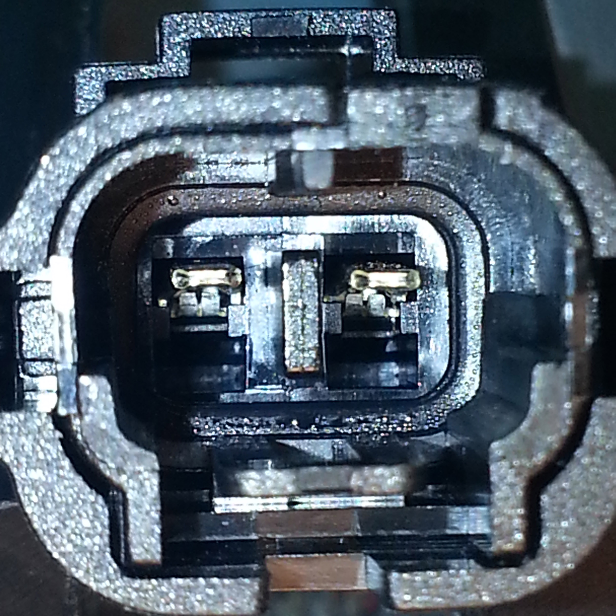
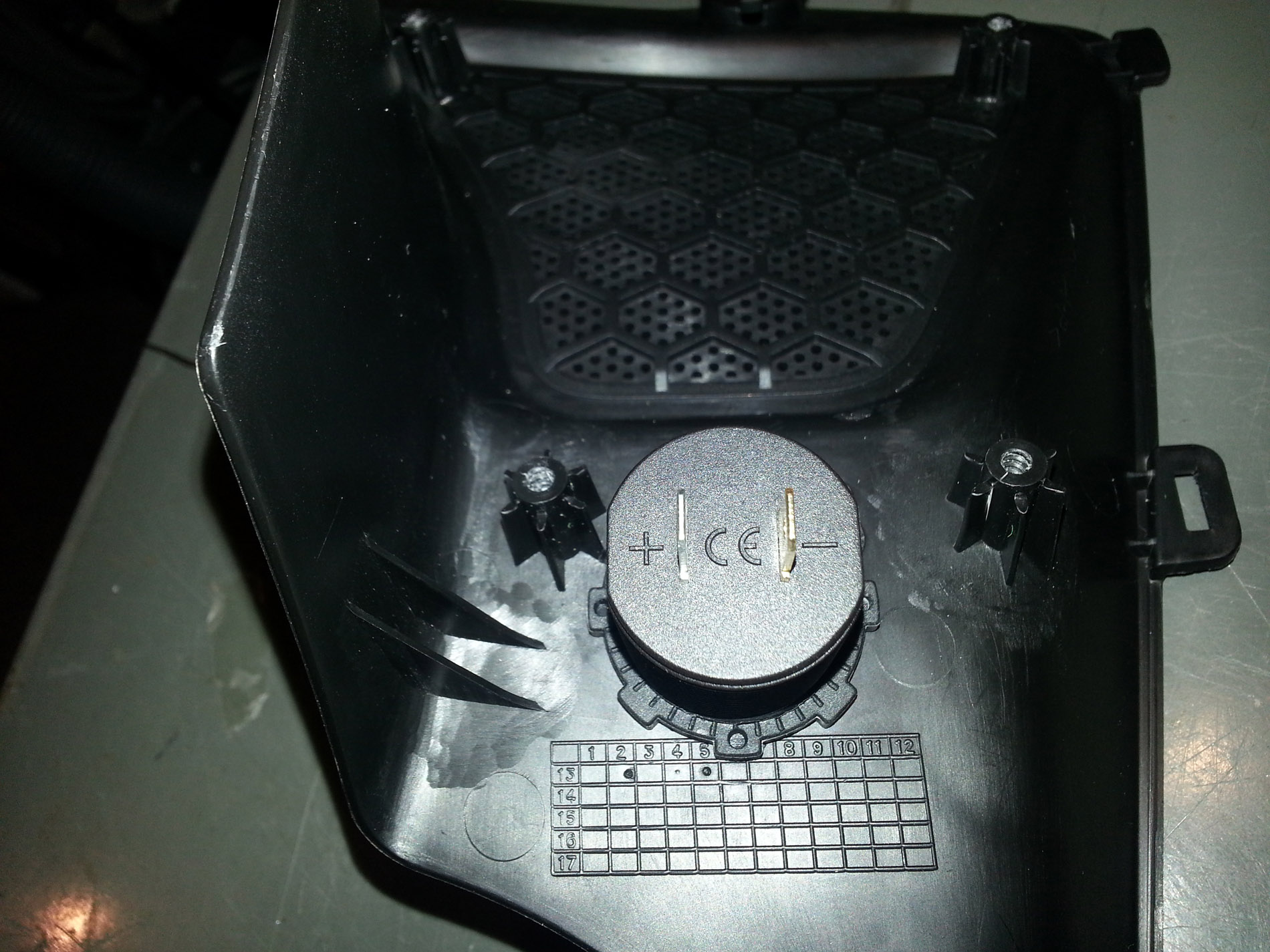
The little dot on the body is negative. |
The pins only go into the shell one way. The pins in the picture are "UP". As the shell is pictured it is also "UP". You can see the little bump in the middle of the shell. That's the locking zone.... |
|
|
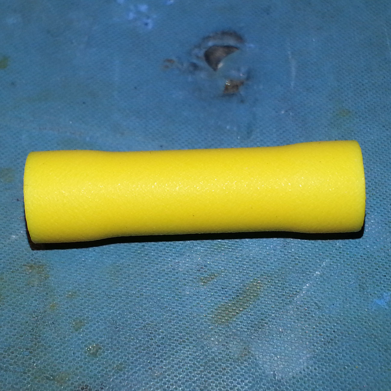
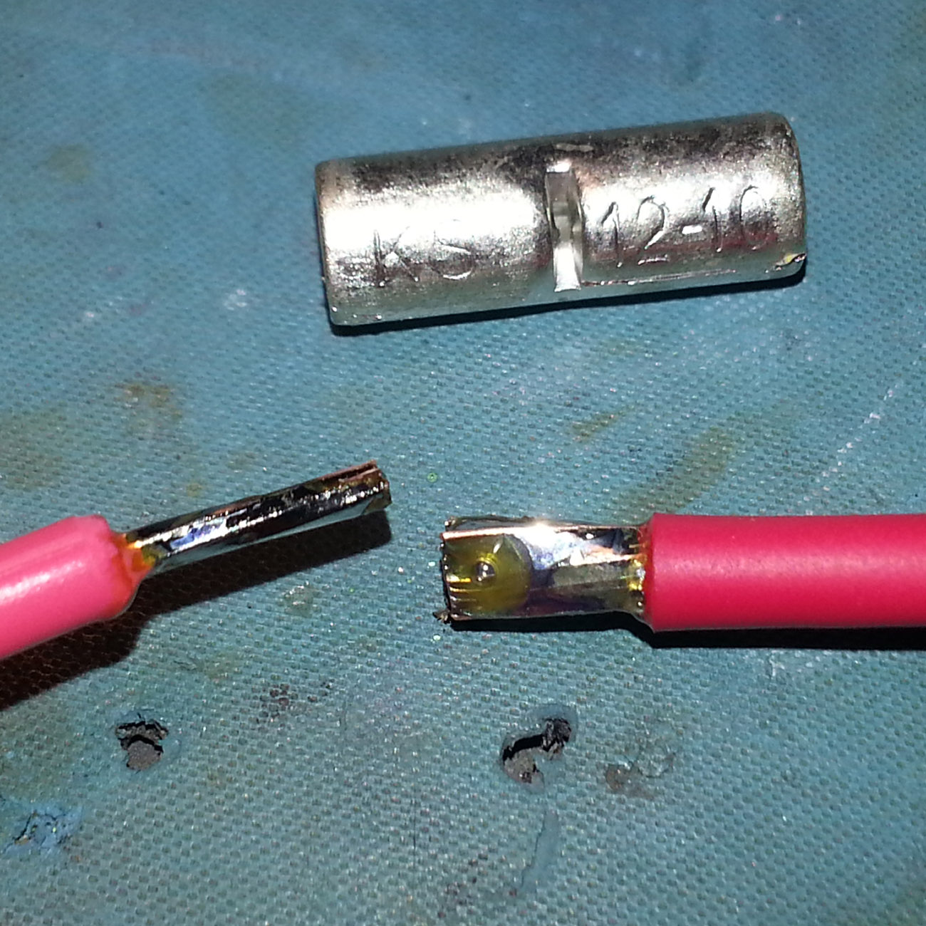
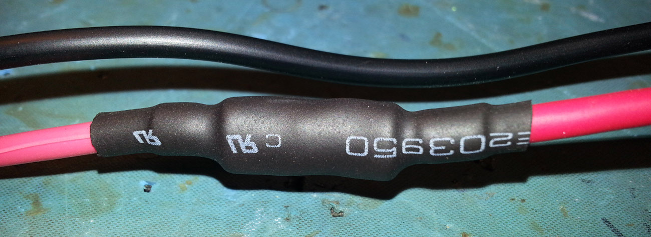
Here's the generic part.... Any auto parts store will carry an inline ATM fuse holder like the one to the left. This one has 12awg wire and is "beefier" than needed but it was the only thing on the shelf. The fuse holder is getting stuck on the end of the cable right before the USB "gizmo". A standard inline splice with the plastic removed is crimped, soldered and heat shrunk to connect it to the end of the cable. |
|
|
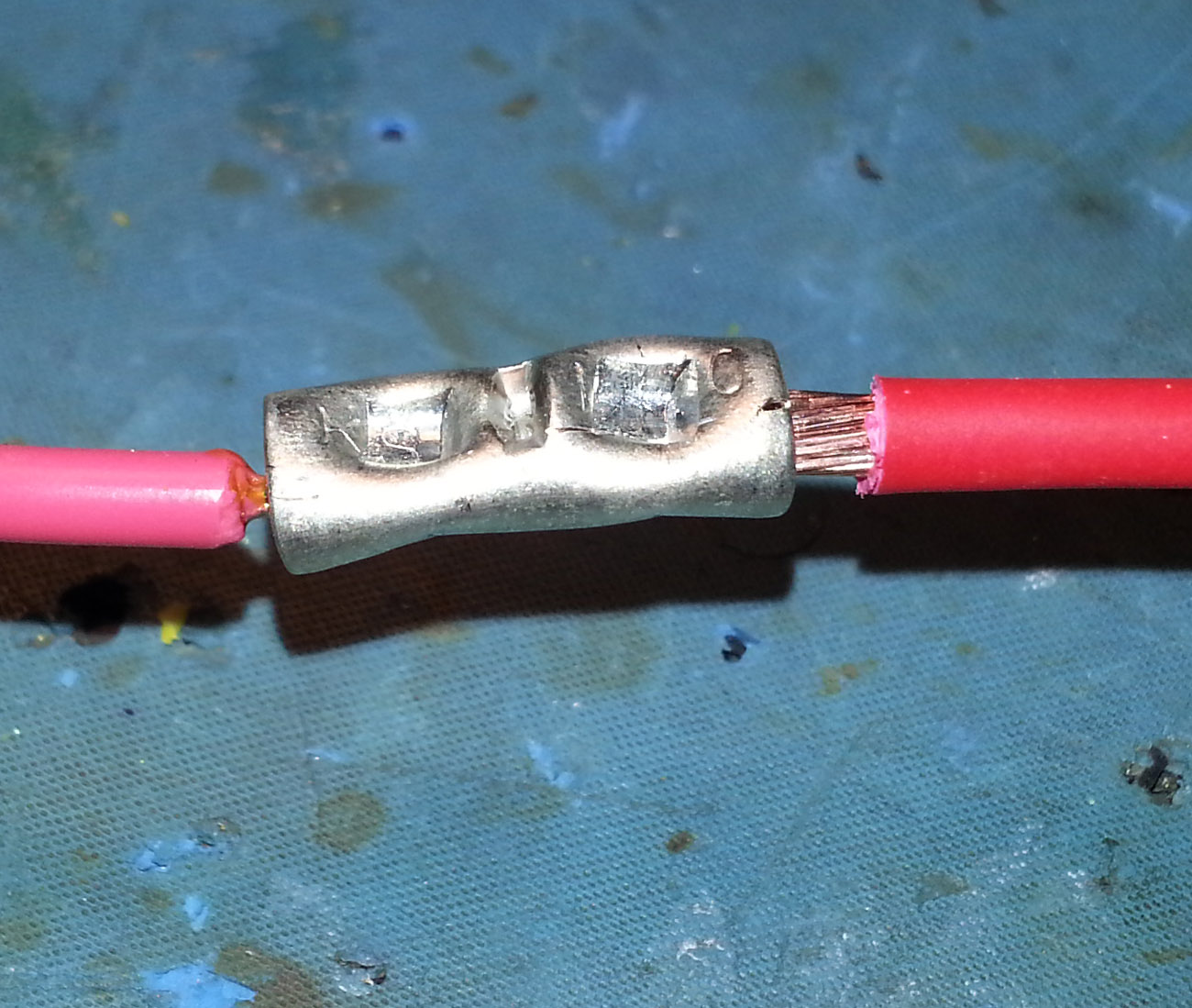
DONT FORGET to add TWO layers of shrink sleeve BEFORE crimping! The first layer is slightly shorter than the second. It makes a nice finished product! |
|
|
|
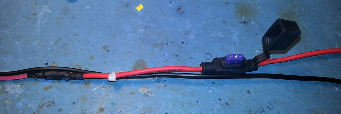
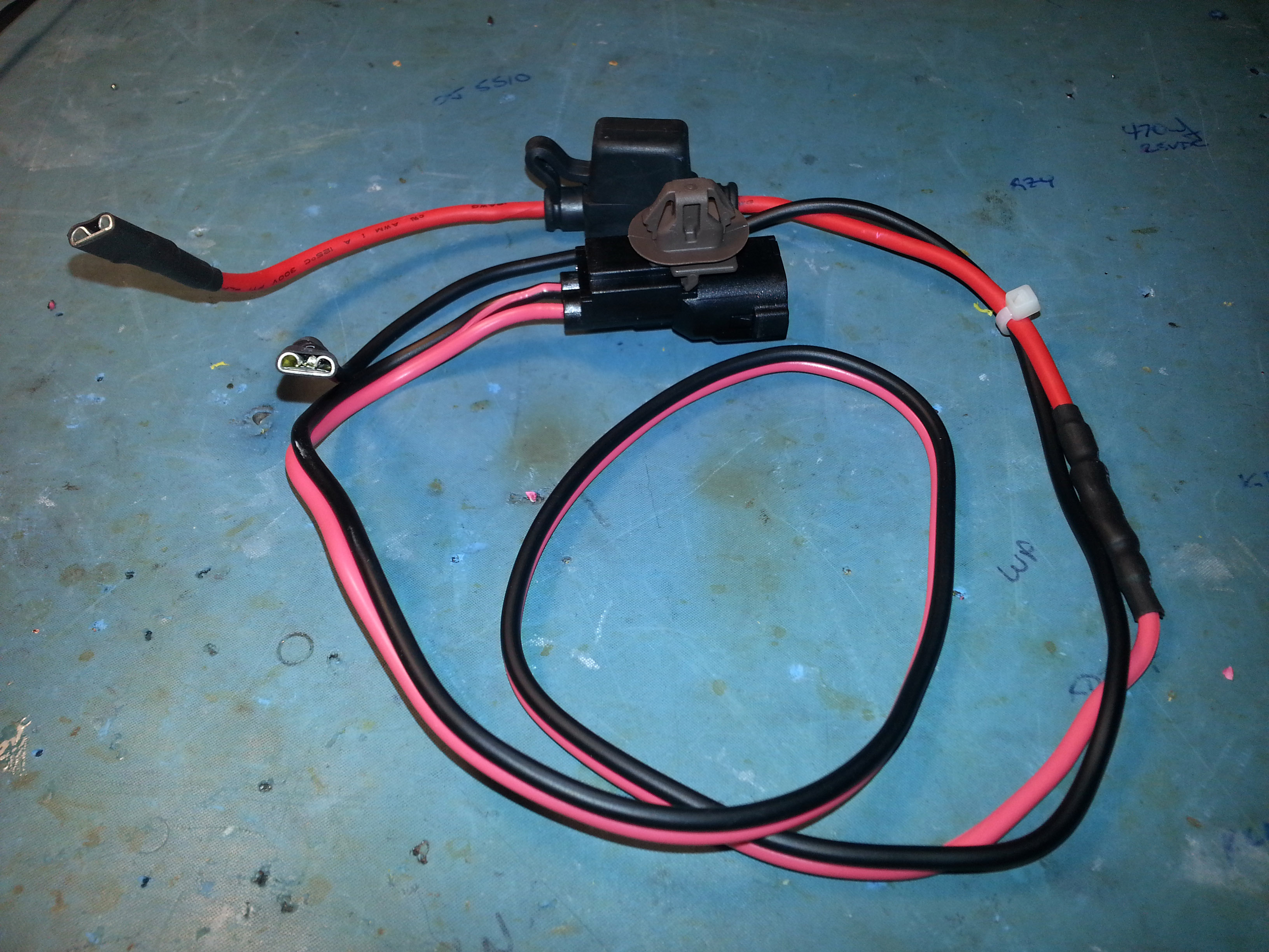
I installed a 3 amp ATM fuse. I doubt my phone or GPS will ever drawn any more current than that. If they do, The fuse holder will be right under the USB device. |
The last thing to add is a pair of .250 female "disconnect" connectors at the USB gizmo end. Shrink Sleeved too!! |
|
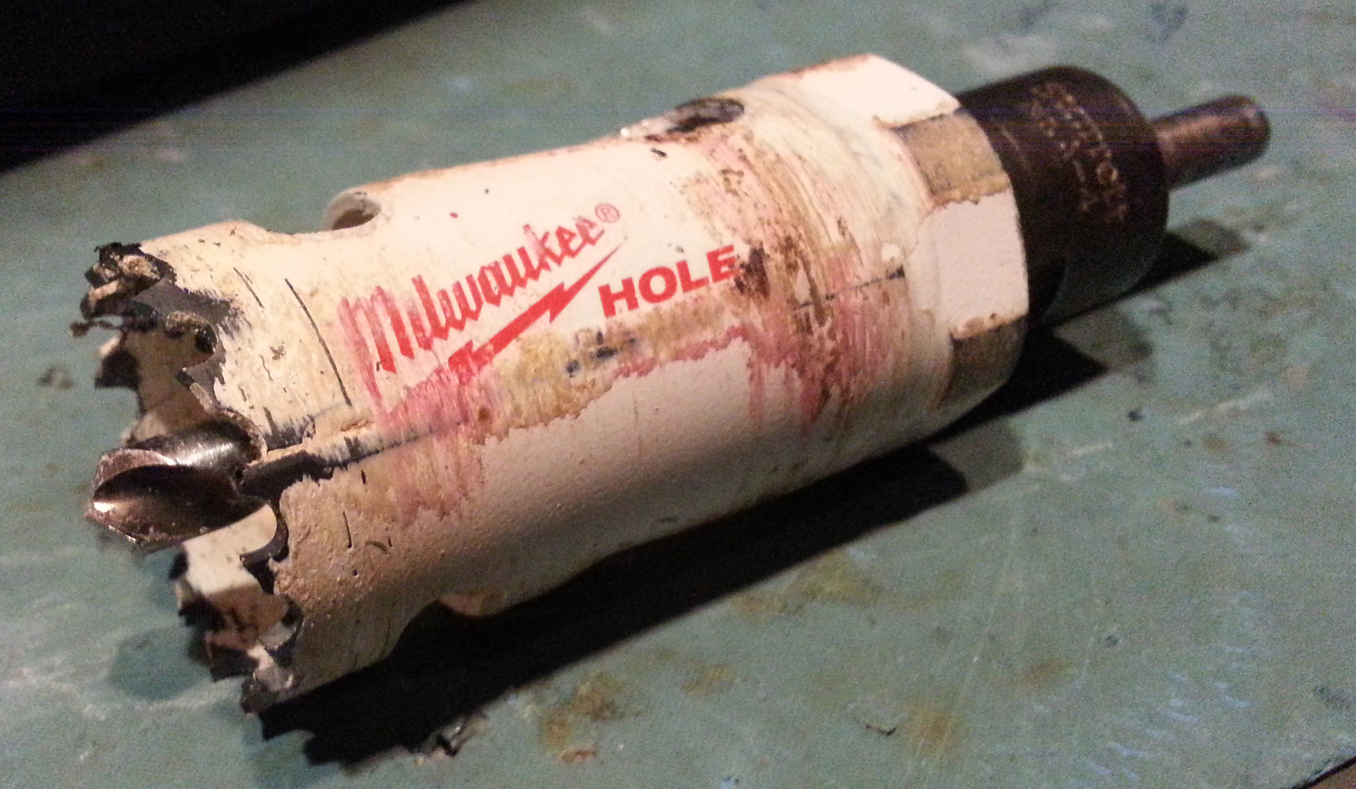
1.125" Hole Saw |
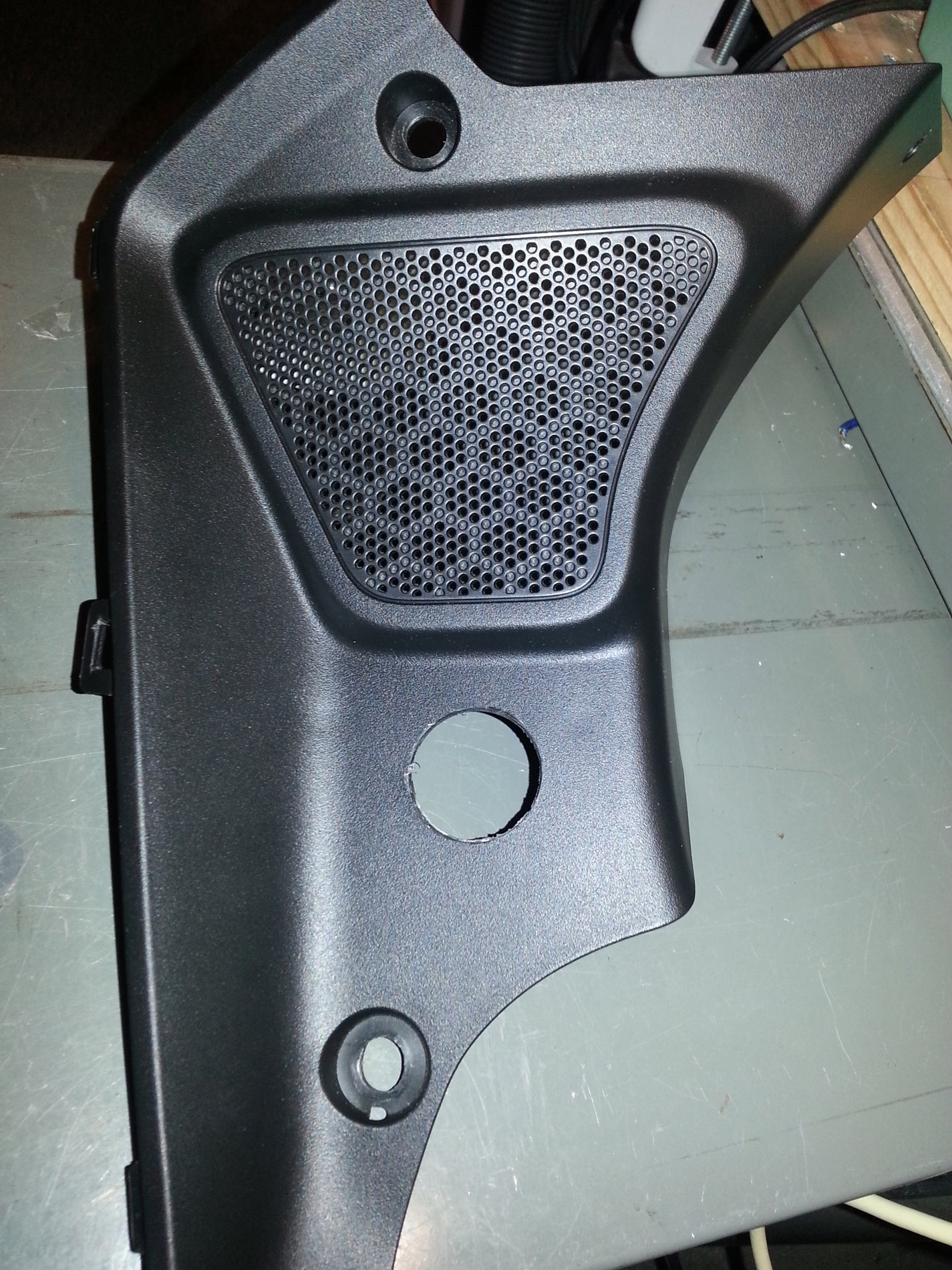
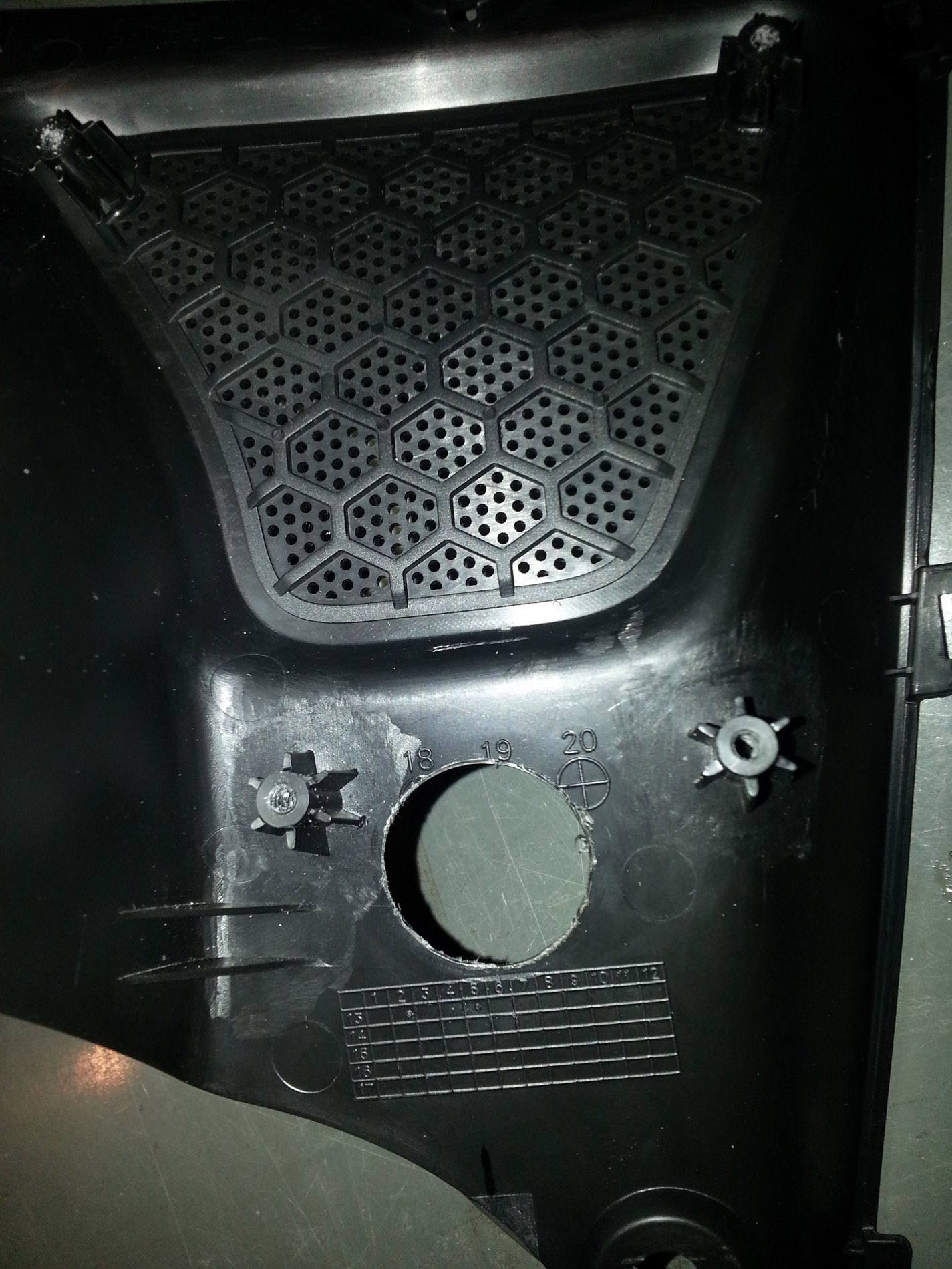
Well, I kinda forgot to take pictures BEFORE I made the hole. What you need to know is that there is a "speaker" plate behind the "grill". The best location (IMHO) is right under the grill. The issue is that the plate kinda presents an issue. |
|
|
What I did was to remove the plate, drill the hole through the main cover then reinstall the plate and use the first hole as a template to cut through the plate. Easy as pie. The plastic is on the softer side so it all went quick. |
|
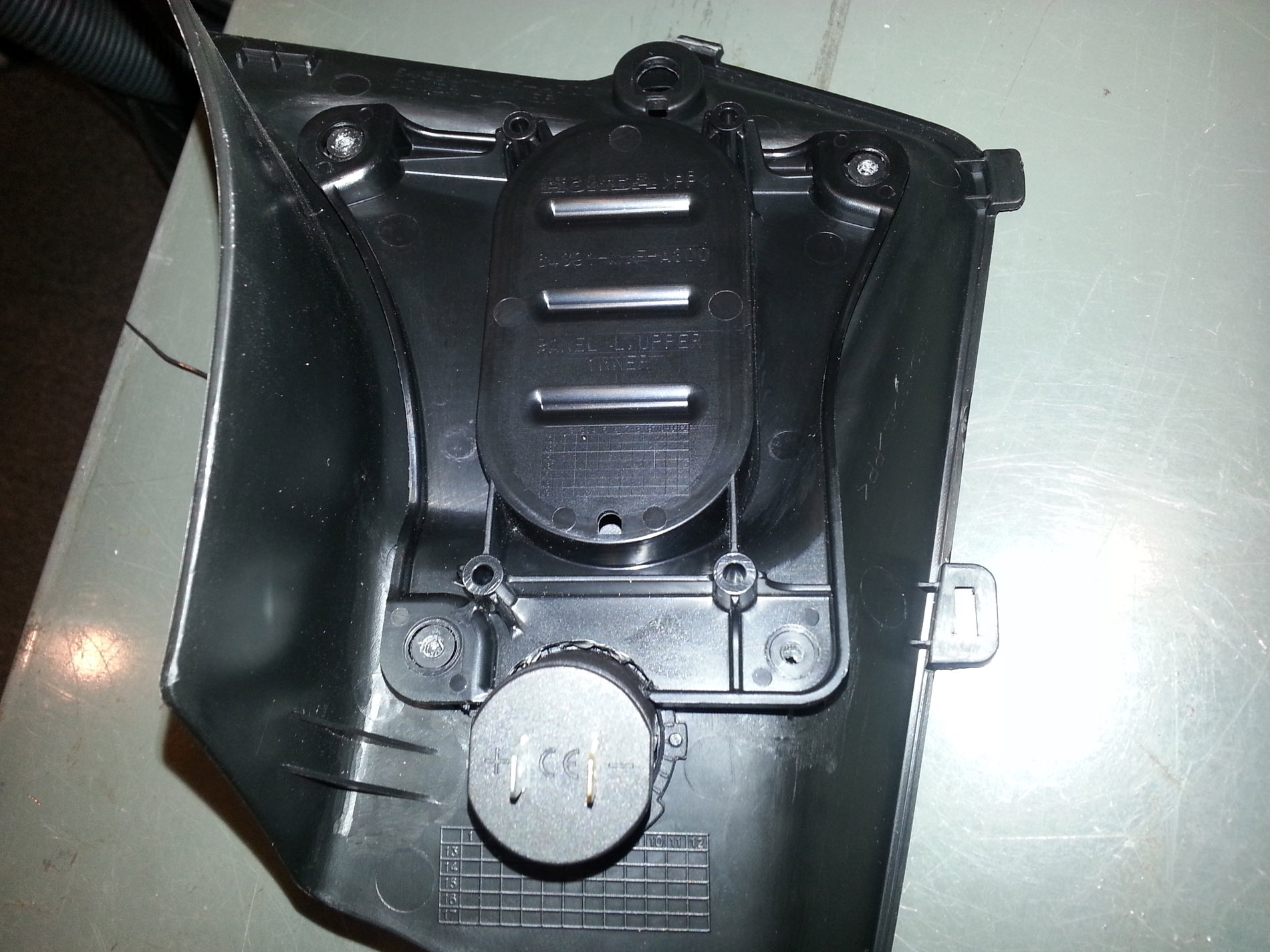
The second picture above has the speaker plate in place. I removed it and drilled the hole as shown to the left of this text. If I would do it over again... I'd drill the hole about another 1/8" inch to the right as you look at the bottom side. The reason is that my location is really close to the left post of the speaker plate. When the locking nut of the USB device goes on it is just a RCH away from that post.... gotta be careful! |
 |
If you click on the picture to the left, you can zoom in and see how close the locking nut is to that mounting post! |
|
With the additional cutout in the speaker plate, it all goes back together easily. |
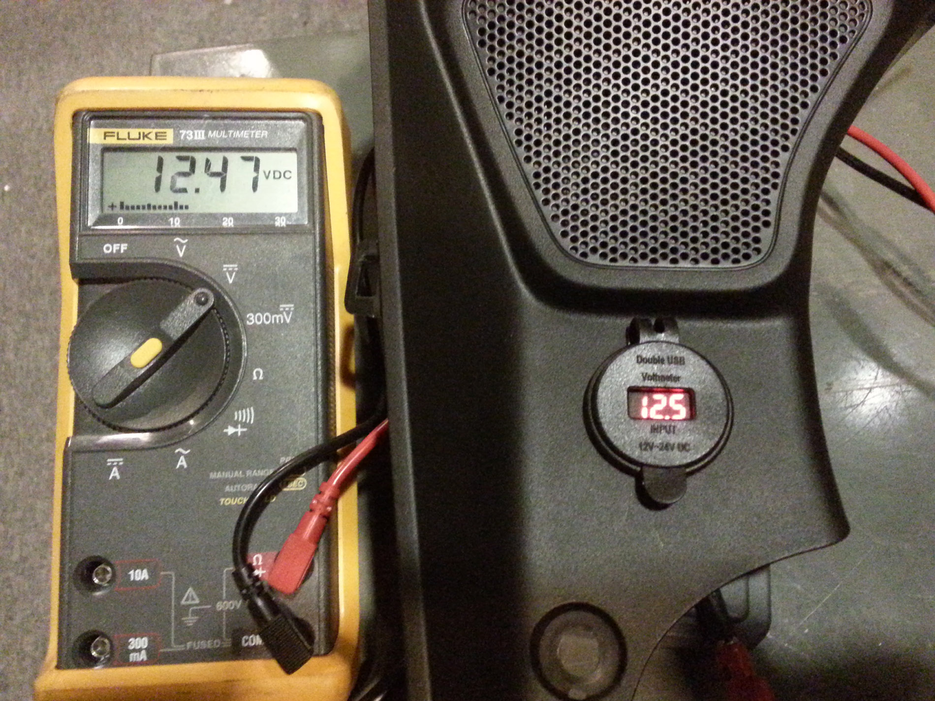 |
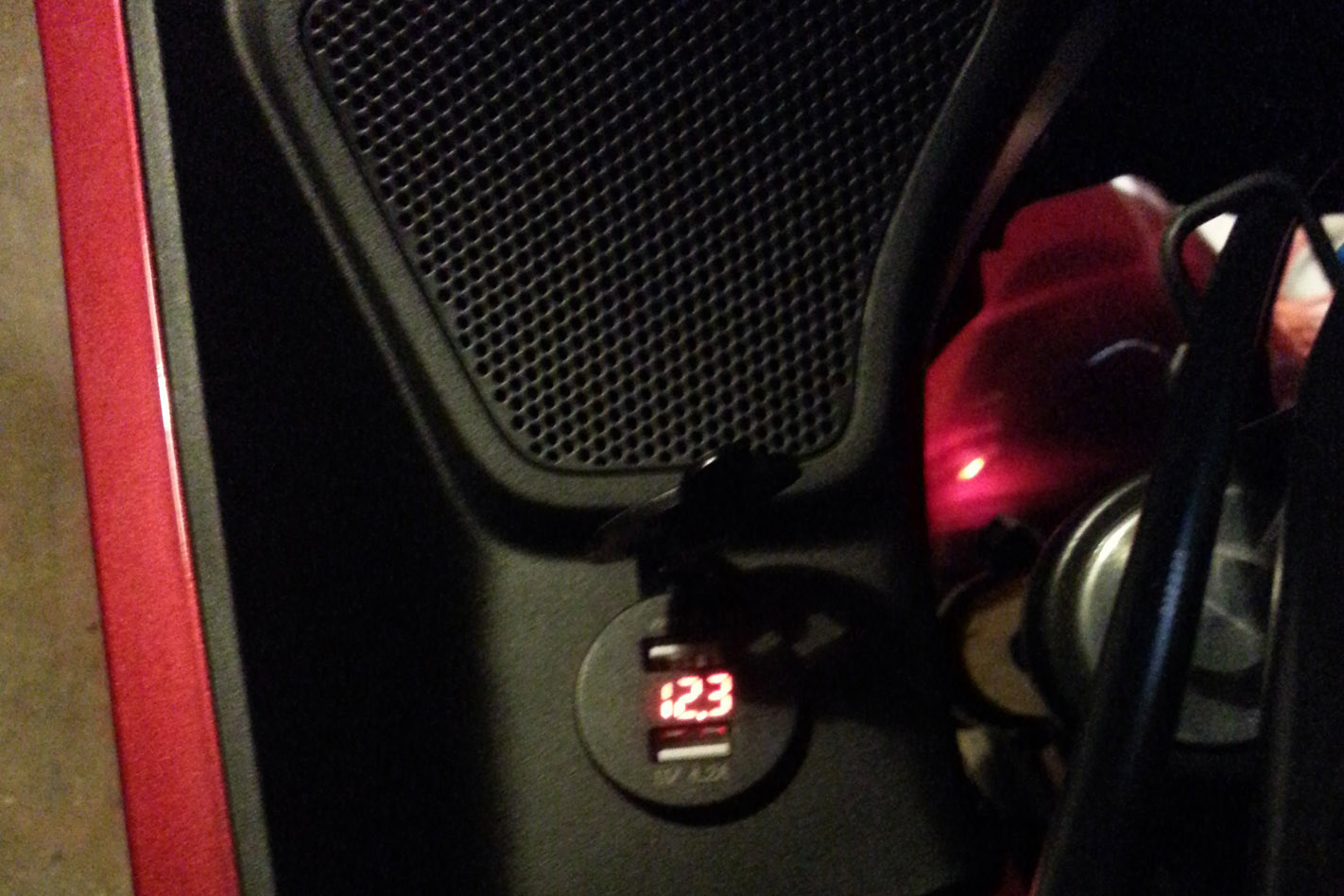
Installing the harness is as simple as sliding the positive and negative connectors on the correct terminals on the rear of the USB gizmo. I bench tested it all before taking it out to the garage. I'd say that the meter is close enough for me! |
|
|
After connecting the harness to the bike, just make sure to click the Sumitomo connector back into the factory locking bracket. I added a few black tie wraps to secure the harness under the panel just to keep things from flying around under there! The pictures to the left are engine off and engine on.... |
Here's the Garmin is a NUVI LM57. I didn't spend a fortune on it just in case Murphy stops by and steals it or it bounces off down the highway! The mounting bracket was from Ebay. The exact name of the thing was " GN032+SPH+WPCS-5D: Motorcycle Mount & Case for 5" Garmin Nuvi, TomTom GPS". It was sold by "GPSlot". For $15 it was a steal. The connecting cable is the only burp in the design. |
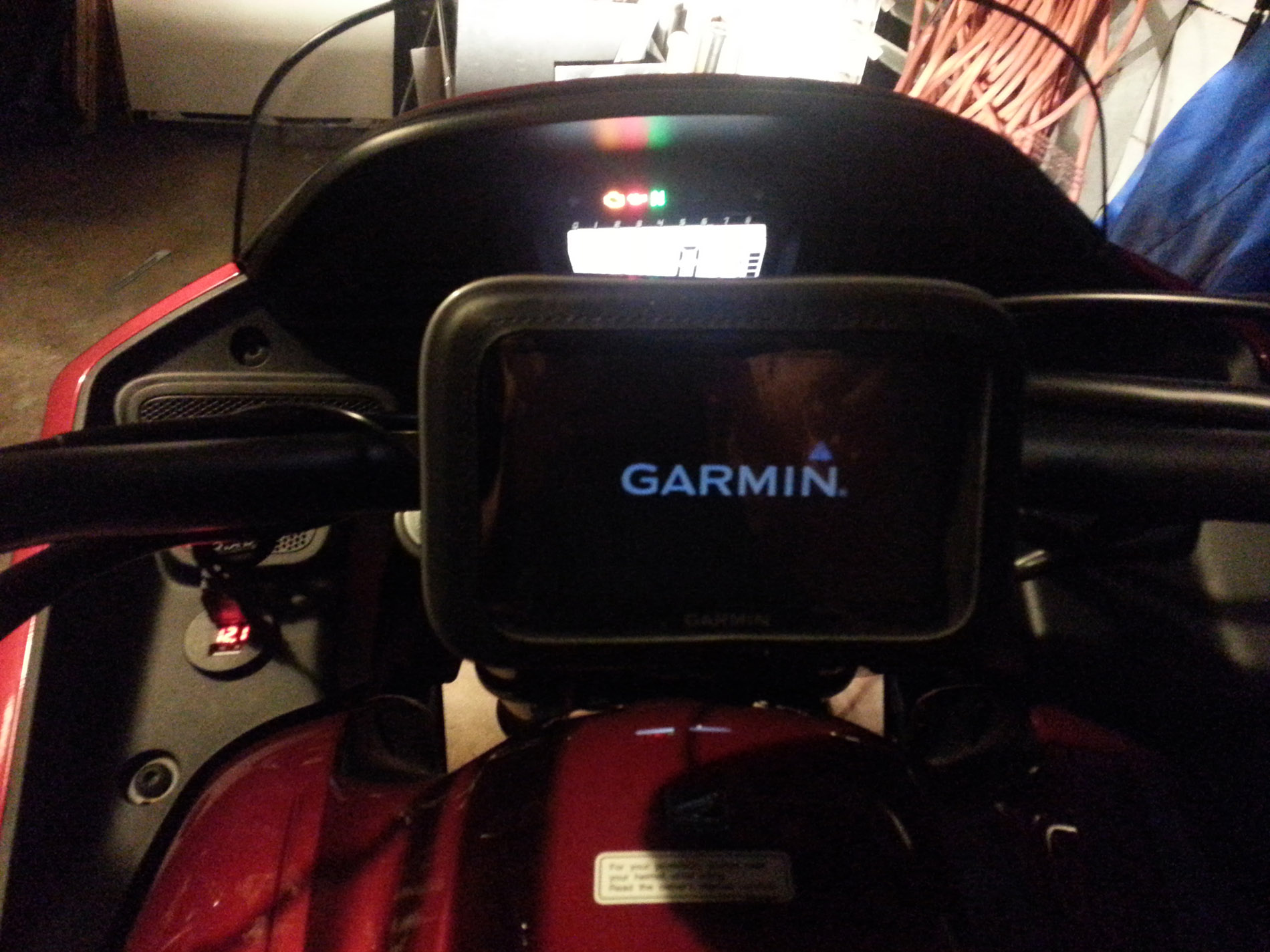 |
The cable that comes with the Nuvi has a 12 volt cig plug on one end and a mini USB on the other. The cig plug drops the voltage to the USB standard of 5 volts. As I found out the hard way... you need to buy a "Garmin" power cable to get the Nuvi to charge from the socket. The small USB connector is a non-standard pinout that causes alll the problems. The other way is to take a normal cable and split the small connector end with an Exacto knife then access the pins and install a Radio Shack 22k resistor between the black wire pin and the one next to it. Use heat shrink to make it all neet and form a 90 degree bend while your at it. I used an 18k resistor because its what I had. It all works perfectly now. The Garmin works with gloves inside the case and it powers up and shuts down with the bike.
|
| |
|
| |
|
| kb2umj at yaa whoo? dot com November 6th, 2016 |
Edit 4/26/2021 |
|