


- Motorola Maxtrac 50 or 100 - Two Channels.
- Motorola Maxtrac 300 - 6, 8, 16 or 32 Channels.
Look
for a radio with a model number that starts with D(n)3MJA(n)(n)
where (n) is a number, with the first (n) usually
3 or 4, but you sometimes see a zero - and the
higher the number, the higher the power. My first
choice would be a radio with a blown up PA section
but fully operational otherwise. Note that any
mobile radio (not just a Maxtrac) does NOT make a
good repeater or high duty cycle link transmitter.
See the "Limitations" paragraphs about 2/5 down
the page at http://www.repeater-builder.com/motorola/maxtrac/maxtrac-intro-stuff.html.
Here's a short breakdown of the model numbers relevant to this modification. There's more to the breakdown than what is shown here, but for the purposes of this article what's here is enough.
Here's a short breakdown of the model numbers relevant to this modification. There's more to the breakdown than what is shown here, but for the purposes of this article what's here is enough.
| Sample Model Number: D43MJA7JA5AK | ||||||
| Mounting | Power | Band | Series and Mode | Channels | Extra | |
| D Dash |
||||||
| 0 (zero) 2 watts |
3 144-174 Mcs. (see note 1) |
MJA1 MJA7 MJA9 All are Conventional |
3 Two Channels (see note 3) |
(see note 4) | ||
| 3 25 watts |
AHA5 MQA5 MQA7 MWA5 All are Trunking (see note 2) |
7 Six Channels (see note 3) |
||||
| 4 45 watts |
D 16 Channels (see note 3) |
|||||
| J 32 Channels |
||||||
Notes:
|
||||||
There are three different RF boards that are commonly found in a VHF Maxtrac:
-
HLD4321B - this is a 136-162 MHz RF board that is VERY rare. Please do not modify it - trade the perfectly good 2m or CAP radio for a 146-174 model.
- HLD4322B - this is the most common RF board out there. It covers 146-174 MHz and is ideal for this conversion.
- HLD4322C - This is the later version of the previous one above. It covers 144-174 MHz and is also rather rare. Please do not attempt to convert one of these radios to 220 MHz. Trade the unmodified radio to someone else for a 146-174 model.
Note
that the RF board and the PA deck are paired, and
the PAs cover either 136-162 MHz or
144-174 MHz. Please do not use a
136-162 MHz RF board or PA deck for this
conversion - they are too valuable and are good
trading material - they are a natural for MARS or
CAP or your local Emergency Operations Center or
Emergency Management Agency radio group. Please do
not hack and slash at one for this mod. A while back
I saw someone trade two 146-174 radios for one
136-162 radio.
Any RF board that starts with HLB is used in a low band radio, HLC is mid band, an HLE is UHF, an HLF is for 800 MHz and a FLF is 900 MHz.
Maxtrac radios can have one of 5 logic boards. If
you find a 16-pin accessory connector you are home
free - only one logic board had the 16 pin connector
and it is the HLN9313A or B, and can do 32 channels
in stock form. Note that the radios that have a
16-pin accessory connector DO NOT have the internal
speaker connected by default - it takes a jumper
plug to enable it. More details (including a photo)
will be found on the Maxtrac Introductory
Information page and in the Interfacing articles.
The 5 pin accessory connector was used on the rest
of the boards. Maxtracs came with 2, 6, 8, 16 and 32
channels and you will have to look at the number
stamped on the logic board to determine the
capabilities of the particular board you have. The
HLN9123A or B is limited to 6 or less channels. Look
at the other articles on this web site for
information on how to expand the channel count on
the HLN5173A or B or HLN9313A or B boards. The fifth
logic board you may find is the FRN5229A or B board
and it is unique to the 900 Mhz radios - and is
mentioned here only for completeness - if you find
one it is of use only to someone with a
900 MHz radio.
Please make sure that the radio meets specifications and operates properly before starting the modification procedure - especially in the areas of receiver performance and deviation of the PL, DPL and voice. You don't need to be in a situation where you have a modified radio and don't know if the radio was good to start with. This modification changes the front end, the VCO frequencies and the PA deck. Modifications to the VCO can drastically affect the modulator and due to this we recommend that the PL, DPL and voice deviation be verified before putting the modified radio into service.
The Radius and GM300 series radios will do Channel Steering, the Maxtrac will not. Channel Steering is the name that Moto Marketing gave to a method of remote channel selection. You enable it in the radio programming, then you send open collector parallel binary to certain pins on the accessory connector to select a channel. This is a natural for remote base applications.NOTE: The author believes that this modification procedure should be applicable to a 146-174 MHz Radius mobile (the D(n)3LRA series) or a 146-174 MHz GM300 (the M(n)3XVC (2 channel) or M(n)GMC or M(n)GMR (16 channel) series) but until he has actually had one on his bench and converted one he is not going to commit to it. Note that there are 136-162 MHz Radius and GM300 mobiles that, like the Maxtrac, should NOT be traded rather than converted. There are also narrowband GM300s that should be left for (and traded to) the EOC and EMA groups.
The channel steering feature in the Radius LRA mobile requires a 16-pin logic board and Version 21.01 firmware or later. The Radius RSS and firmware only offers three channel select input lines, not five like the GM300 (one line gives you 2 channels, 2 lines gives you 4 channels, 3 gives you 8, and 4 gives you 16). The three channel select lines on a Radius limits you to 8 channels (channels 1 through 7 plus whatever the front panel has selected - and don't count on the front panel selection staying put during a power cycle). Personally I only program 7 channels in a Radius based remote base.
If you have a Maxtrac and can locate a copy of the Radius version 21.01 firmware, the matching RSS and the matching Lab RSS you can brain-wipe your Maxtrac and make it a Radius.
The GM300 has five input lines and was artificially limited by Motorola marketing to 16 channels. If you patch the RSS you can get 32. This gives you a much more flexible channel steering system with ... if you can get by with 15 channels on 4 lines you can use the fifth line for one additional input function... transmit PL inhibit, for example.
Back to Maxtracs and the 220 mod...
The complete Maxtrac service manual can be downloaded from the Maxtrac page at the repeater-builder web site. It is in 4 PDF files totalling 75 MB. If you chose to modify a Radius mobile that manual is a 28 MB download of a ZIP file containing 10 PDF files. The GM300 manual is also available as 5 PDF files totalling 62 MB.

Please be aware that this document is currently a work in progress which may contain several omissions and or typographical errors.
DO NOT COMMENCE HARDWARE MODIFICATIONS UNTIL THIS DOCUMENT IS RELEASED IN ITS FINAL FORM.
If you continue you are proceeding at your own risk.
Background:
This document expands on the original work done by
Glenn Hochwalt, Jr. W8AK to convert the VHF
Maxtrac into the 222 MHz band. Special thanks
to Jeff Ackerman, KG6UYZ for providing the radios
for experimentation.
Overview: The basic Maxtrac VHF radio uses high side receive injection. With a 45.1 Mhz Intermediate Frequency the receive VCO is just about where the transmit frequency (i.e. the VCO) needs to be for 220. In Glen's initial work he found that it was easiest to just remove the receive and transmit VCO coils and swap them. Testing of the exciter was very encouraging using the receive coils. Next the receiver was attempted. Conversion to low side injection was tried as well as the normal high side. High side injection, despite being technically somewhat more difficult, did allow direct frequency input via RSS and was thus chosen as the method to pursue. Modification of the transmit VCO coils to work in the receiver was required as were modifications to the receiver front end coils. The exciter output coil was also modified to return the output level to its original value. The PA was replaced with an off-the-shelf made-for-220 MHz power brick.
Overview: The basic Maxtrac VHF radio uses high side receive injection. With a 45.1 Mhz Intermediate Frequency the receive VCO is just about where the transmit frequency (i.e. the VCO) needs to be for 220. In Glen's initial work he found that it was easiest to just remove the receive and transmit VCO coils and swap them. Testing of the exciter was very encouraging using the receive coils. Next the receiver was attempted. Conversion to low side injection was tried as well as the normal high side. High side injection, despite being technically somewhat more difficult, did allow direct frequency input via RSS and was thus chosen as the method to pursue. Modification of the transmit VCO coils to work in the receiver was required as were modifications to the receiver front end coils. The exciter output coil was also modified to return the output level to its original value. The PA was replaced with an off-the-shelf made-for-220 MHz power brick.
Phase 0: Preparations
Make
sure the radio to be converted is in good working
order on its original frequencies before attempting
conversion to 222 MHz Amateur Radio use. The
output power does not matter as the entire PA will
be chopped out of the circuit board (therefore a
radio with a blown-up PA deck is ideal for this
conversion), but you will need a working exciter and
driver, and will want to test the transmitter
modulation (including voice and PL / DPL),
the receiver sensitivity, PL / DPL decode
and audio output before starting this modification.
Phase 1: Operating Frequency Reprogramming
I
used Maxtrac Lab RSS R07.02.00A in this project.
Earlier versions were found to work fine with some
versions of the Maxtrac firmware, but would not read
others. If you use a Radius or GM300 radio for this
you will need to use different RSS, and maybe have
to patch it to allow out-of-range programming.
Before you start making modifications to the RSS you
should make an archive copy of it. Before you start
making modifications to the radio's codeplug you
should make an archive copy of the original
codeplug. If you have access to the Lab variant of
the RSS you should use it as well (i.e. make two
backups, one with regular RSS and one with Lab).
Programming the radio is as normal except that when entering the frequency it is necessary to enter the numbers with the shift key held down (except for the decimal point) and all digit places must be filled (i.e. add trailing zeroes as needed).
Example: 223.5 MHz is entered as (shift)223(unshift).(shift)5000(unshft) and appears as @@#.%))) - but you can hex patch the RSS frequency limits to get around that and allow direct frequency entry. There are articles on hex editing / patching the RSS at this web site. Using properly patched RSS makes programming (or reprogramming) the modified Maxtrac or Radius no more difficult than the unmodified radio.
Both the transmitter and receiver will cover the 219-220 MHz (the digipeater band) and the 222-225 MHz band with no adjustments necessary. The VCO will lock across approximately 215-230 MHz for both transmit and receive. The actual VCO lock range for any particular radio depends on the care taken with the modification and the tolerances of the components used in assembling the original radio.
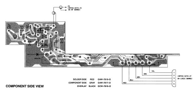
Phase 2: The VCO
Remove the RF board from the chassis of the radio using a Torx T-10 driver.
It will be necessary to use a high heat broad tip
soldering iron such as a Weller 800� PTC to remove
the coils and their housings from the board. This is
best accomplished by melting the solder joints and
slowly rocking the entire coil out of the board.
Hole clean up is best done with the aid of a
stainless steel dental pick, solder wick and solder
sucker.
Steps: (Note that the colors mentioned are what was found in the radios that were modified. Please do not rely on the colors mentioned until you have verified that the ones in your radio match what is listed)
-
Remove L213, the transmitter VCO adjustable coil (Yellow). Label it as "original L213" and set it aside for now.
- Remove L202, the receiver VCO adjustable coil (Orange), and install in the L213 position.
- Remove L215, the transmitter VCO fixed coil (Yellow). Label it as "original L215" and set it aside for now.
- Remove L204, the receiver VCO fixed coil (Orange) and install in the L215 position.
- Remove approximately 3 turns from the top of the original L215 (Yellow), so that it has 2 and one half turns total. Carefully cut the plastic with small flush cut diagonal pliers to release the wire. Bring the remaining lead down the side of the coil and trim to the same length as the opposite lead. Strip the enamel off of the new lead and tin with solder. Install the modified L215 in the L204 position.
- Steps to modify the original L213:
- Extract the plastic housing from the metal shield.
- Disengage the metal tabs by sliding a X-acto knife or small jewelers screw driver inbetween the metal and plastic on the underside of the coil.
- Push coil out of shield by pressing the center hole against a step drill bit.
- On the side of the coil with the most wires apply solder and short the top 3 turns together, be careful not to melt the plastic too much.
- Apply solder to the top 2 turns on all the other sides. Take care that the solder does not extend from the plastic too much so it will not short against the shield, if necessary reheat or file the solder down.
- Replace the shield and install the modified L213 at the L202 position.
- Remove L221 from the board. Remove 3 turns from the top and bring the remaining lead down the side of the coil and trim to the same length as the opposite lead. Strip the enamel off of the end of the new lead and tin with solder. Reinstall the modified L221 in its original position.
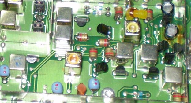
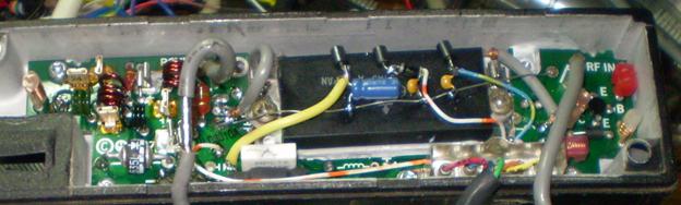
The Modified VCO section
Replace
the RF board into the radio chassis for testing
purposes.
If desired a PLL unlock LED may be added to the board, just take a red LED and solder a 330 ohm resistor on the anode. Slide the lead of the resistor into J6, Pin 5 and the cathode of the LED into J6, pin 11.
Test the receiver VCO by coupling the signal to a spectrum analyzer or frequency counter. Use a loop of wire or an antenna connected to the input of the test equipment. Connect a voltmeter to �SV� test point. Tune the coil at the L202 position (Yellow) with a non-metallic tool until a stable on-frequency local oscillator is observed (receive frequency + 45.1 MHz). A stable voltage on the �SV� test point should be approximately 7.8 Volts.
Some additional tuning range can be achieved by bending the coil at L215 on its side. See the photo above.
Take a 47 ohm resistor and bend one lead over so both leads are on one end. Trim leads so center the center one comes out approx 3/16� and the side one is flush with the end of the body. Insert modified resistor into the transmit VCO jack on the RF board.
PTT the radio and tune the transmitter VCO by coupling the signal to a spectrum analyzer or frequency counter. Use a loop of wire or an antenna connected to the input of the test equipment. Connect a voltmeter to the �SV� test point. Tune the coil at the L213 position (Orange) with a non-metallic tool until a stable on-frequency signal is observed. A stable voltage on �SV� should be approximately 7.8 volts. Remove the resistor from the transmit VCO connector when the testing is completed.
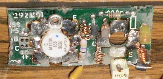
Phase 3: The Low Pass Filter
The
original Low Pass Filter is designed for a corner
frequency of approximately 205 MHz which is
appropriate for a high band radio, but not for
220 MHz. Bend a turn off the end of each of the
LPF coils (L2x62, L2x61, L2x60 and L2x51) and lay
the turn approximately 45 degrees away from the rest
of the coil (look for the two brown coils in the
photo below, and the green coil that is in between
them). The single turn from L2x62 should be nearly
flat with the printed circuit board (see the left
end of the green coil under the word "ANT"). These
changes will bring the 3dB corner up to
approximately 235 MHz which is right where we
need it.
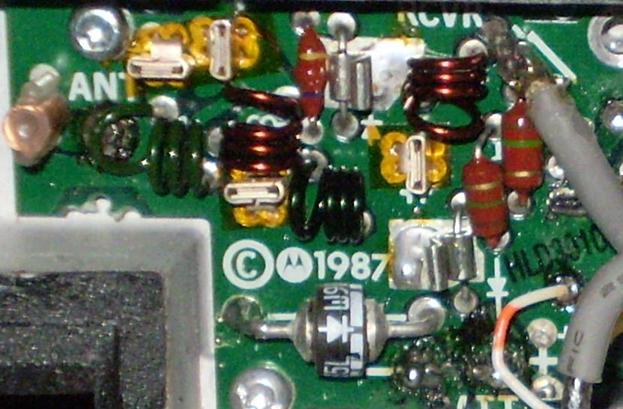
Modified Low Pass Filter (45W VHF Power Amplifier)
The
filter can be optimally tuned by connecting a
spectrum analyzer to the PA, sweeping into the
antenna port and detecting the on the receiver
cable. A test jig was made by plugging the receiver
lead into a BNC barrel and soldering a spot of the
ground ring to the BNC connector.
 Click image. |
 Click image. |
| Low Pass Filter
before modification. (showing a 12dB loss at 225.000 Mhz) |
Low Pass Filter after modification |
Phase 4: The Receiver
Remove the RF board from the chassis again.
Mark the shields for L1 through L7 both as to
location and orientation. You will want to get them
back on the way that they came off. Remove the
shields and the coil from L1 through L7 using the
procedure described earlier. On the side with the
most wires visible apply solder shorting out the top
two turns. This must be a small solder blob so as to
not short the coil to its shield. Reinstall modified
coil in board without the shield for initial testing
and proceed to modify the other coils.
The initial checkout of the conversion can be tested with all shields removed. Reinstall the RF board in the chassis. Using a service monitor check the receiver sensitivity. Additional turns of coils may be shorted for optimum performance. My receiver came to -110dB for 12dB SINAD without any additional tuning. If satisfactory reinstall the metal shields on all the coils.
When complete install 7 each 6-32 x 1/2 inch brass screws into the top of the plastic forms of L1-L7. Be very gentle doing it, the threads do match. The brass screws allow fine tuning of the front end filter. With the screws inserted the radio was able to make 12dB SINAD at -118dBm, 20dB at -115 dBm and the squelch threshold was set to -120dBm where the measured SINAD was 6dB. Note that the squelch adjustment is an internal trimpot.
Note from WA6ILQ:
I've seen (but not had a chance to get a picture of) a Maxtrac where the owner very carefully removed the front panel, then removed the speaker, then drilled a small hole right in the center of the cone area, and mounted a 1/8" shaft potentiometer in the center of the grille, then wired the pot in place of the PC board mount pot, then reassembled everything.
So a front panel squelch pot is possible on a Maxtrac, Radius or GM300... you just have to find a pot that is the right value, and shallow enough to clear the speaker cone.
Phase 5a: The 2W VHF Power Amplifier
The 2W VHF PA should make the rated 2 watts of
power at 222 MHz without any modifications.
Some additional tweaking of L2362, L2361 and L2360
may be done until maximum power output is achieved
as observed on a watt meter.
Phase 5b: The 25W VHF Power Amplifier
See Phase 5c.
Phase 5c: The 45W VHF Power Amplifier
Remove
the PA board from the heat sink. Desolder the
power connector by unscrewing it from the heat
sink, heat both pins and slowly rock it out of the
board. Remove all Torx screws and the nut on the
rear holding Q2430. Desolder the antenna jack and
pull the board from the housing.
The 45W VHF PA would not cooperate on 222 MHz. It is believed the final transistor is not designed for operation above 175 MHz. It was determined the best course of action is to cut away a section of the printed circuit board and install a made-for-222 MHz power brick.
The 45W VHF PA would not cooperate on 222 MHz. It is believed the final transistor is not designed for operation above 175 MHz. It was determined the best course of action is to cut away a section of the printed circuit board and install a made-for-222 MHz power brick.
| Module Part Number | Power Input | Power Output |
| M57774 | 300mW | 30W (Class C) |
| M67712 | 200mW | 30W (Class AB) |
| M68729 | 300mW | 30W (Class C) |
| RA30H2127M | 50mW | 30W (MOSFET) |
| SAV15 | 200mW | 30W (Class C) |
| SAV40 | 50mW | 30W (MOSFET) |
Depending
on the power module you have available will
determine how much of the PA board is cut away. I
used the M67712 which is easily obtainable from
old 220-222 MHz ACSSB and Linear Modulation
Radios. Because this module needs 200mW (+23dBm)
of drive we need the first amplifier stage of the
PA.
Remove Q2450, L2421 and cut the board like this:
Remove Q2450, L2421 and cut the board like this:
A Dremel tool with heavy duty cut-off wheels is the recommended armament.
The removed portion of VHF 45W Amplifier board
Salvage
3 Ferrite beads from the cut board and surrounding
areas and solder them to the DC input leads of the
power module. 1st VCC voltage is
obtained from the Controlled B+ line, 2nd
VCC is at the C2444, R2471 junction and Vbias is
from 9.6T through a single 1N4004 diode to drop
the voltage to 9V.
When using a power amplifier module that requires 50mW of input (such as the RA30H2127M) the first stage is not required and may be eliminated. So cut the board like this:
Salvage
2 Ferrite beads from the cut board and use them
them on the DC input leads of the power module.
VCC voltage is obtained from the C2444, R2471
junction, and Vgate is from 9.6T through a 100 ohm
resistor into a 1N4733 5.1V zener diode to ground
diode to drop the voltage on Vgate to 5V. A 7805
or other 5v regulator may be used instead.
Some traces were cut through as hte PA section was removed so those will need to be patched with wires to restore the circuitry. Patch the Current Sense Lo line between C2444, R2471 junction and C2402, and patch 9.6T for the PIN diodes between R2450 and R2452.
The Maxtrac heat sink must be machined flat to accommodate the new power module. I really suggest going to a machine shop for this. In additon to the milling I used a Dremel tool with a high speed cutting bit to flatten the mounting stud for Q2430.
Note: The mounting plate of the power module itself should also be machined flat, otherwise the surface will not conduct heat well enough, nor does it have good contact with ground.
Drill 2 holes and tap for 6-32 screws for securing of the module to the heat sink. Use screws with large diameter heads, or use washers to provide a large tightening surface. The idea is to distribute the pressure. I installed the M67712 with the leads facing the side wall of the heat sink to accommodate shorter coax and power leads; you may desire to orient your module the other way.
Remove C2450 and install a short run of RG-174 mini coax to the RF output of the power module. Install a spade lug on the module end of the coax ground to attach to the screw holding the module in place.
Remove L2420 and install a mini coax from the power input of the module to the C2421 and C2420 junction. If using RA30H2127M salvage the original RF input coax from the cut piece of board and install it on the power input of the module. Install a spade lug on the module end of the coax ground to attach to the screw holding the module in place.
Apply a fresh coating of thermal compound to the heat sink and screw the module in place as well as the PA board.
As shown in the photo below a ground wire is soldered over the power module to for the connection of the ground side of the bypass capacitors. This should probably be made from coax braid to improve ground impedance, but I used a 24ga wire as it was handy. I used 0.1uF capacitors on both Vbias and 1st VCC, and a 10uF 25V on 2nd VCC.
Some additional tweaking of
L2462, L2461 and L2460 may be done until maximum
power output is achieved as observed on a watt
meter.
Phase 5d: Modifying the 2W VHF Power Amplifier to 30W
Cut the board and modify the amplifier in similar
fashion to Phase 5c. Replace R2371 with a 0.01 Ohm
2W resistor. The junction or R2371 and C2378 will
provide either VCC or 2nd VCC depending
on the power module chosen.