
A detailed explanation of the accessory connector of
the MaxTrac 300, Radius and the GM300 Mobil Radios.
The top article is from information provided by Neil Johnson WB�EMU
The two white-background articles at the end were received as e-mails by Repeater-Builder.
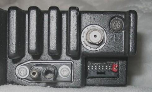
This view is looking at the radio accessory connector,
bottom of radio down.
The red jumper is shorting pins 15 and 16.
The exposed pin on the power connector is the positive
pin.
The pins are numbered as per the above diagram.
You may find a jumper on pins 15 and 16 to enable the speaker, either as a official Moto jumper plug in the connector (as below), as a PC style 2-pin jumper buried in the connector (as shown in the photo above), or as a jumper wire or as a solder blob inside the radio.
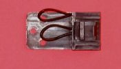
The above photo is of the official Moto jumper plug... the
top jumper is between pins 15 and 16 to enable the
internal speaker. The lower jumper (pin 9 to 7) in the
photo grounds the alarm pin (e.g. forces it idle no matter
how the radio is programmed). The holes in the plastic tab
are for a tie-wrap that goes through them and around the
cable jacket as strain relief.... outer holes for fat
cable, middle hole and one outer hole for smaller diameter
cable.
On various radios I have found the real Maxtrac jumper plug, on others I've found a PC style jumper on the two pins (as shown in the above photo - and which is NOT appropriate for a mobile environment), on others a soldered wire jumper (or even just a solder blob) on the back side of the board bridging the two pins.
Note that Moto used the same jumper plug on several different series of radios, and the wiring was different for each. One of these anomalies is the GTX series (see the CAUTION note below). If you find one of these plugs in a box somewhere be sure and verify the wiring before you plug it into any radio.
You can make up your own cables:
The plug body and pins are made by AMP Corporation, a huge
manufacturer of every type of connector from Mil-Spec to
travel trailer connectors to ribbon cable to ....
The connector body is their part number 104422-1, and the
pins are 1-87309-3, however they won't talk to you unless
you want to buy very large quantities..
So we go to DigiKey or Mouser...
| Digikey: | Connector body, with locking tab, 16 pin:
104422-1-ND ($1.46 singles, $1.22 each for
a pack of 25 in April 2006) Contact: A3007-ND (about 14 cents each or about $12.50 per hundred in mid to late 2005) |
| Mouser: | Connector body: 571-1044221 ($1.41 singles,
$1.27 each in quantity ten, in April 2006) Contacts (pack of ten): 571-1873093 (about $1.25 in April 2006) |
Note:
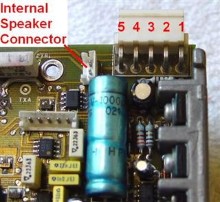
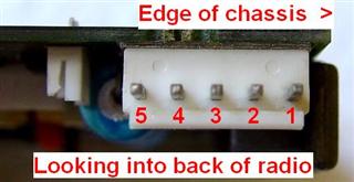
1) J3 is the 5-pin accessory connector.
2) J10 is the connector inside the radio between the
internal speaker and the logic board.
Also remember that Moto's RSS software will let you do things the radio can't - make sure you don't have the same function (i.e. PL / CTCSS decode or PL Encode Disable) programmed for more than one pin on the accessory connector. The RSS will let you do it, but if you do, the radio doesn't work right... Add this to your programming checklist: before you upload into the radio you should review the programming looking for function duplication.
Here are photos of the 5-pin accessory connector: from the top of the board, from the rear of the board, and the accessory plug that fits it:
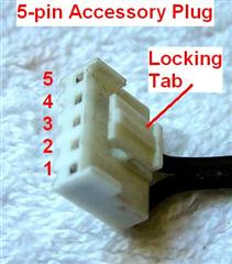
The Mouser part numbers for the 5-pin connector are:
Connector body: 571-111237225 ($0.20 in May 2008)
Contacts: 571-11237211 or 571-11237212 ($0.13 in May 2008)
In the Pin # column in the following table, the numbers in parentheses are for the accessory plug on the 5-pin logic boards (J3).
| Pin # |
Name | Notes | ||||||||||||
|---|---|---|---|---|---|---|---|---|---|---|---|---|---|---|
| 1 (1) |
EXT SPKR - | This accessory connector pin provides the return for an external speaker. It is the same function as J3-1 of the five pin logic board. To use an external speaker with the radio you would hook it from this pin to pin 16. Note that both sides of the speaker are hot and floating. | ||||||||||||
| 2 | MIC AUD | This signal is
parallel with the MIC HI line at J8-12. It is
normally an input. This pin can also be an output
when the radio�s microphone is used for P.A.
announcements. Sensitivity: 80 mV rms for 60% deviation (i.e. 3 kHz dev) at 1 kHz. Frequency response: +1/-3 dB referenced to a 6 dB per octave pre-emphasis characteristic from 300 to 3000 Hz. In other words, the audio entering at this point is pre-empahsized in the audio chain. Since this pin is paralleled with mic jack, if a source other than a microphone is connected to this input, it must not load down the micorphone - don't provide less than 600 ohms dc resistance to ground (it must not pull the dc voltage on this pin to less than 4 volts). Otherwise the microphone mute gate Q651 may be driven to cut-off during portions of the applied audio signal waveform, causing severe distortion. You might also want to insert a 10uf coupling cap (positive side toward radio) in series with this line to block the DC voltage (used to power the preamp internal to the microphone housing) that may affect the external audio source. |
||||||||||||
| 3 | MIC PTT | This signal is
parallel with the radio�s MIC PTT line at J8-11.
This pin may serve as an input where a ground
applied to this pin keys the radio or as an output
to sense the MIC PTT status.
|
||||||||||||
| 4 (3) |
Programmable Output Only | This is a radio output
port. It is an open collector output which
saturates to A+ supply when active. It is normally
used to drive an external relay or sense lead. It
duplicates the function of J3-3 of the five pin
logic board. When active it can source a maximum
current of 250 mA. The pin has a 10 K ohm resistor pull-down to ground on the logic board. and uses a PNP transistor to switch it up to 12V. This pin does not work as an active low pin (i.e. pulling something to ground), only as an active high (that is dragging something up to +12v). If you want an active high output to drive a reed relay which has the other side of the coil to ground, this is your pin (but don't forget to check that the backwards diode is present on the coil pins). |
||||||||||||
| 5 | FLAT TX AUDIO | This signal is routed
via a coupling cap to TXA pad (R704). This audio
input is flat (not pre-emphasized). This pin can
be used to send external CTCSS or DCS audio
signaling or as a flat input from a receiver that
delivers un-processed audio.
|
||||||||||||
| 6 | Programmable Input Only | This signal is
connected via a transistor level
shifter / protection circuit to
microprocessor input pin #32 (with interrupt). As an input, a voltage between 3 and 16 volts is recognized as a logic high and less than 1 volt is recognized as a logic low. This pin has a 4.7 K ohm resistor pull-up to 5 Volts on the logic board. One of the programming options for this pin is as a transmit PL Inhibit. The Radius and GM300 offer Channel Steering on this pin. |
||||||||||||
| 7 (1) |
Ground | This pin is used as both the audio and digital ground. The standard 16 pin accessory jumper plug has this pin jumpered to pin 9 to keep the Emergency Switch input grounded (inactive). | ||||||||||||
| 8 | Programmable Bidirectional | This is a radio input
or output port. As an output it is an open collector MMBT3904 surface mount transistor which saturates to ground. It can sink a maximum of 200 mA. The low level will be 0.3 V max. It is driven by gate array pin #38. As an input, a voltage between 3 and 16 volts is recognized as a logic high and less than 1 volt is recognized as a logic low. The input is applied to gate array pin #25. The input has a slow rise time constant of 1.0 msec. This pin has a 4.7 K ohm resistor pull-up to 5 Volts on the logic board. One option on this pin is programming as an ANDed COS and PL decode signal (active high or active low). Remember that the PL decode is dependent on the mic "hang-up" signal. This can be simulated by a RJ45 mic jumper with pin 3 (PL Defeat) jumpered to pin 4 (ground). The Radius and GM300 offer Channel Steering on this pin. |
||||||||||||
| 9 (2) |
Programmable Input Only | This signal is
connected via a transistor level
shifter / protection circuit to
microprocessor input pin #44 (with interrupt). As an input, a voltage between 3 and 16 volts is recognized as a logic high and less than 1 volt is recognized as a logic low. This pin has a 4.7 K ohm resistor pull-up to 5 Volts on the logic board. This input is normally used for the EMERGENCY SWITCH (input) and is functionally the same as J3-2 of the five pin logic board. The standard 16 pin accessory jumper plug has this pin jumpered to ground (pin 7). Once you remove the EMERGENCY SWITCH assignment in the RSS you can remove the jumper and use this pin as another general purpose input. The Radius and GM300 offer Channel Steering on this pin. |
||||||||||||
| 10 (5) |
IGN CTRL | This input controls
the entire radio on/off operation. It has the same
function as J3-5 of the five pin logic board.
Logic board jumper F801 must be removed to
implement ignition control. Current drain is less
than 500 mA. If programmed active the radio will not power up until this pin is high to +12. In repeater, remote base or link duty I recommend that it be programmed inactive. If you find a jumper to +12 inside the radio you can pull the jumper and reprogram the radio. |
||||||||||||
| 11 | RX AUDIO | This pin is labeled
"DISCR" in the Moto dcoumentation, and provides
receiver audio output and is controlled by the
position of JU551 on the logic board near the
audio output transistors. When JU551 is installed
in position A the output is flat (not
de-emphasized) and is not muted by the radio
squelch. When in position B the output audio is
both squelch muted and de-emphasized. The jumper
is normally shipped in position A. I've also found
this jumper missing on some radios. In most
applications you want the de-emphasized position.
Note that there are three jumpers on the board,
labeled JU551, JU601 and JU808, so if you need to
change the mode of the audio make sure that you
move the correct one. See the photo below.
|
||||||||||||
| 12 | Programmable Bidirectional | This pin is selectable
by P808 - a push-on jumper which is normally in
the PROG I/O position, labeled "A" on the board.
In the PROG I/O position the pin connects to a
radio input/output port. The output is an open
collector MMBT3904 surface mount transistor which
saturates to ground. It can sink a maximum of 200
mA. The low level will be 0.3 V max. As an input, a voltage between 3 and 16 volts is recognized as a logic high and less than 1 volt is recognized as a logic low. The input is applied to microprocessor pin #22. This pin has a 4.7 K ohm resistor pull-up to 5 Volts on the logic board. The Radius and GM300 offer Channel Steering on this pin. Alternately this pin can be jumpered to the SCI+ circuitry (labeled "B") and connects in parallel to J8-7 (i.e. the programming pin in the front panel microphone jack). Serial Communications Interface (SCI) is a bi-directional interface that is normally used to program the radio using a RIB and a PC running the proper RSS. In SP applications, the jumper could be removed, and the center pin of the jumper block (which is tied to pin 12) could be wire-wrapped to any required point in the radio. |
||||||||||||
| 13 | SW A+ SENS | Connects to J8-5 which supplies switched +12 power from the radio on/off switch. This output can be used to sense the powered state of the radio or to activate or power accessory devices (such as a TNC). This pin can deliver about 1/2 amp... If you overload this pin you can blow the internal fuse. | ||||||||||||
| 14 | Programmable Bidirectional | This is a radio
input/output port. The output is an open collector
MMBT3904 surface mount transistor which saturates
to ground. It can sink a maximum of 200 mA. The
low level will be 0.3 V max. It is driven by gate
array pin #39. As an input, a voltage between 3 and 16 volts is recognized as a logic high and less than 1 volt is recognized as a logic low. The input is applied to gate array pin #24. The input has a slow rise time constant of 1.0 msec. This pin has a 4.7 K ohm resistor pull-up to 5 Volts on the logic board. The Radius and GM300 offer Channel Steering on this pin. |
||||||||||||
| 15 | INT SPKR + | Connects directly to
J10-1 (the internal speaker). No other connection.
It supplies audio to the internal speaker (through
a series 1-ohm limiting resistor). The standard 16 pin accessory plug has this pin jumpered to pin 16. |
||||||||||||
| 16 (4) |
EXT SPKR + | This radio output
provides 3.16 V rms into a 2- ohm load (5 Watts).
In other words, this is the audio PA output. It is
the same function as J3-4 of the five pin logic
boards. The standard 16 pin accessory plug has this pin jumpered to pin 15. |
||||||||||||
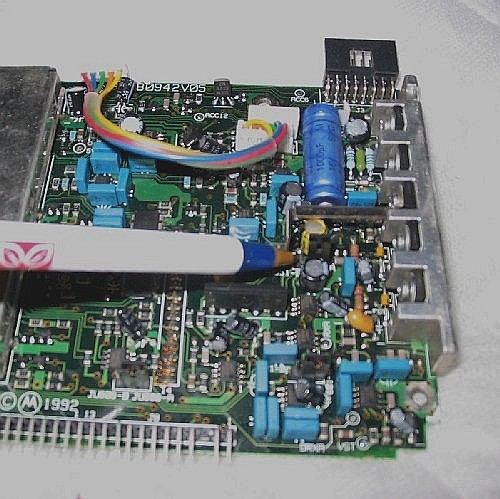
This is JU551 referenced in the description for pin 11.
From an e-mail received by Repeater-Builder:
|
! ! ! CAUTION ! ! ! If you insert an accessory plug wired up for a GTX mobile (pin 13 jumpered to pin 16) into a MaxTrac, then turn the radio on, the big, shiny, blue 1000uF 16V capacitor in the photo above will have about 6-7 volts DC of reverse-polarity voltage applied to it. After about a minute, maybe less, it will blow up, releasing smoke and all sorts of nasty chemicals, some of which may not be healthy to humans or to the circuit board. It may also short out and cause further damage to the logic board, especially to the audio output transistors. Please heed the warning at the end of the MaxTrac main page about not using accessory plugs wired for GTX radios in MaxTracs. Luckily (for a change), putting a MaxTrac-wired plug into a GTX will not cause such catastrophic damage. Editor's note: Yes, the above happened to a friend of a friend of repeater-builder. If it happens to your radio, you really want to get the crud off the board quickly. I keep a quart can of Methyl-Ethyl Ketone (a.k.a. MEK, available at good hardware and paint stores) under the bench just for board cleanup, and refill it as needed from a 1-gallon can in the garage. Now mind you, MEK is not healthy when inhaled everyday for years like in a PC board repair environment, but there is no problem for short periods and outside (read: "good ventilation and downwind") and when wearing gloves. I have a pair of wrist length kitchen "Bluette" brand rubber gloves lying on top of the can, along with a box of cheap Q-tips to get the MEK around the parts... Plus there is a compressed air hose to dry it off. And in my case the side door of the shop and an outside workbench is less than ten steps away from the inside bench. Use your head and think of MEK as a very occasional cleaning solvent, not as everyday hand soap. |
From another e-mail received by Repeater-Builder:
|
Customizing the Expanded Accessory Connector This information has been extracted from the official MaxTrac manual noted below: RSS Part #: RVN-4019-K and the matching
manual #: 68P80900Z03-J Background: The Expanded Accessory Connector's pin functions may be modified in RSS on the ACCESSORY CONNECTOR CONFIGURATION screen. Press F9 at the RADIO WIDE CONFIGURATION screen to display this screen. Customizing the expanded accessory connector becomes necessary when more than one accessory requires programmable functions or a non-standard accessory is used. The display also contains useful information on the characteristics of each function. Functions available on this screen are Data Direction, De-bounce, and Active Level.
Programming De-bounce: De-bouncing is usually required for pins that are driven by relay contacts or other mechanical switching devices. Functions that have De-bounce as "NO" (or off) should not use relays or mechanical devices to drive them. To change De-bounce, move the cursor to the De-bounce data field for the pin that needs to be changed. Use the up/down arrow keys to change from de-bounce on ("Y") to de-bounce off ("N") or vice versa. Programming the Active Levels: The programmable pins are binary. They become active on either a high voltage or a low voltage. Some non-standard accessories may not have the same active level as the default active level. However, the RSS allows the active levels to be changed. To change an active level, move the cursor to the Active Level data field for the pin that needs to be changed. Use the up/down arrow keys to change the active level from high to low or vice versa. High voltage in this sense means 5-15 Volts DC; low voltage means 0-0.5 Volts DC. All signals are a positive voltage referenced to ground (pin 7). "Active high" means that the voltage is low (or ground) when the signal is inactive (or off) and high when active (or on). "Active low" means that the signal voltage is high when inactive and low (or ground) when active (or on). Independent versus Dependent Functions: Each programmable pin on the Expanded Accessory Connector has a limited number of functions that can be assigned to it. There are two type of functions: independent and dependent. Dependent functions cannot be reprogrammed. They depend on the assigned pin when used with the selected accessory. Independent functions can be reprogrammed. Available Functions: The table below lists the accessory connector input and output functions. Each function has a function number assigned to it. This number is used to assign a function to a pin. The tables below can be used to determine which functions are necessary for your application. Using this table and the ACCESSORY CONNECTOR CONFIGURATION screen, you should be able to configure the accessory connector to suit your needs. On the ACCESSORY CONNECTOR CONFIGURATION screen, move the cursor down the function number column (denoted by the # in the table below) to the desired pin. Use the up/down arrow keys to select the desired function. Notice that description, data direction, de-bounce, and active level change according to the function. The NULL function is used to de-activate a programmable pin. AVL is an abbreviation for Automatic Vehicle Locator system which is a generic term for any of the several commercial versions of APRS. The "Dir" column indicates input (I) or output (O). Accessory Connector Pin Functions
Programmable I/O Pins: The Expanded Accessory Connector has six programmable I/O pins to allow it to adapt to various accessories. For ease of programming, commonly used accessories have their pin functions predefined and can be programmed on one data field. Some accessories will need to be programmed on a pin-by-pin basis. The RSS provides screens for customizing your application pin by pin. Internal Accessories are accessories that are physically placed inside the radio and that do not actually use the connector. Connections are made internal to the radio but the pin functions are still used. At the time of this writing there is only one Internal Accessory: the DTMF decoder board. If the Internal Accessory field is set to DTMF, the decoder should be installed in the radio before you begin programming. Possible Pin Assignments for Independent Functions
Internal DTMF Decoder: The DTMF decoder board kit, model HLN3146A, must be used with an HLN9313A logic board, since this is the only logic board that has the 16-pin accessory connector and the feed-through holes on the board. The kit consists of the DTMF decoder board: HLN9376A, a six-conductor cable and connector assembly: HKN9362A, hardware (screws, standoffs, nylon washers): HLN9459A, and the manual: 68P80900Z88. Six wires from the cable are soldered to the following feed-through holes on the logic board: +5V, GND, ACC8 (serial clock), ACC12 (serial data), ACC6 (data ready), DRXA (audio input). An addendum to the manual moves the audio input from DRXA to one end of R543. The DTMF board mounts behind the display board in the front panel, on standoffs that replace the original display board mounting screws. |
||||||||||||||||||||||||||||||||||||||||||||||||||||||||||||||||||||||||||||||||||||||||||||||||||||||||||||||||||||||||||||||||||||||||||||||||||||||||||||||||||||||||||||||||||||||||||||||||||||||||||||||||||||||||||||||||||||||||||||||||||||||||||||||||||||||||||||||||||||||||||||||||||||||||||||||||||||||||||||||||||||||||||||||||||||||||||||||||||||||||||||||||||||||||||||