
The UHF Maxtrac can have one of two different RF boards:
the HLE4425A or B which covers 403-430MHz - perfect for
420-430 links and control channels, or the HLE9310A or B
which covers 449-470MHz. Unlike the high band Maxtrac
where two of the three RF boards cover 2m with no tweaks
at all (and the third can be stretched) the UHF radio
needs some work to have good performance from
440-450MHz. It doesn't take much - most, if not all, of
the 449-470 Mhz Maxtrac or Radius
M100 / M214 / M216 series
radios will cover the ham band down to 440 Mhz.
In some cases you will even get one that will
cover 438-450 MHz. What I am about to show
you is how to touch up the tuning of your average
Maxtrac or Radius M100 / M214 / M216
to make it reliable in the ham band.
If you have the money, and the test equipment to do so, then you may want to get a service manual from Motorola and do a full alignment. But, for the rest of us, a little screwdriver work goes a long way! This is not a professional and all-inclusive alignment of the radio, but rather just a VCO adjustment to allow use of the radio outside of the specified 449-470 MHz range. If you're picky about receiver performance than by all means do a full alignment! The ones I have performed this work on perform just as well as other radios I own. I have the attitude of "If it ain't broke don't fix it!"
I am going to assume that:
a) You have a UHF Maxtrac on the bench, connected to a
dummy load, and powered by a power supply capable of
supplying sufficient current.
b) You have read the "Upgrading" article for the background
information.
c) You have the Maxtrac RSS running on your old slow
computer.
d) it is successfully talking through the RIB to the
radio.
In this article I will cover in general all the areas you need to go to fully program the radio. I will show the RSS screens that you should visit to verify settings, as well as hardware adjustments after getting past the initial programming.
First of all, you need the Motorola Maxtrac RSS, and version R07.02.00.A is the preferred one as it allows out-of-range frequencies (i.e. below 449 MHz) to be entered simply by holding the shift key down while entering the numbers. For example, to program a frequency of 440.00000 MHz just hold down the shift key and enter "$$)" for 440 then release the shift key and enter the decimal point then press the shift key down again and enter the five trailing zeros ")))))" and then release the shift key and hit enter.
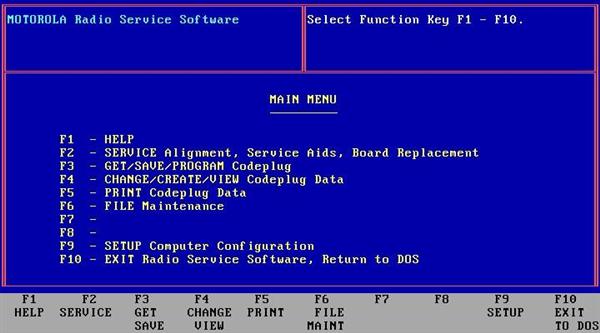
First thing you should do is connect the radio and RIB to the computer and run the RSS.
| The RSS
starts at the Main Menu. Hit F3 to go to the Get/Save/Program menu. |
 |
| Hit F2
to read the codeplug from the radio. When it is done it will return to the Get/ Save menu. |
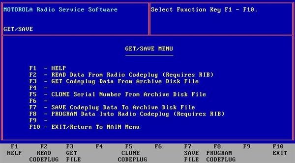 |
| At this time you should hit F7 Save codeplug data to archive to a file on your hard drive. | |
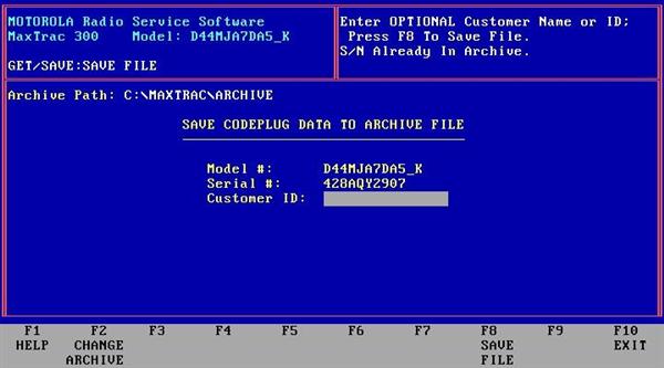
| If you
haven't already set the save path do so, and
then type in a customer id (maybe your
callsign?) and hit the F8 key to save the file. When its done saving it will bring you to the file backup screen. You can use this to backup the file to a floppy disk to have a backup copy in the event that the one now saved to the hard drive location you specified in the previous screen is lost. |
 |
On to programming!
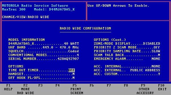
| Now hit F10 until you are back at the main menu, then hit F4 Change/Create/View codeplug data, then F2 Radio Wide configuration. | 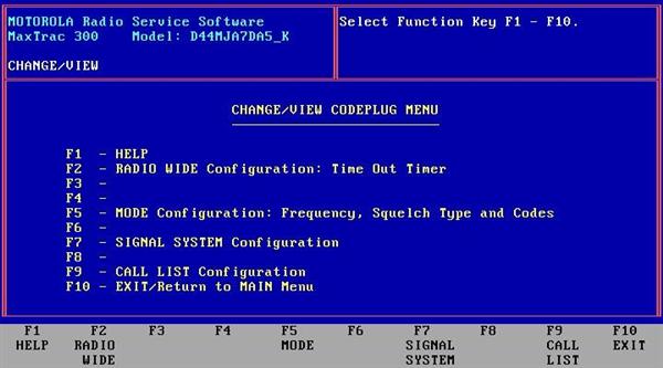 |
| Here you
can select things such as time out timer,
priority scan, signaling options, etc. From this screen hit F9 to take you to the other accessory screen. |
 |
| This is
the page I mentioned in my 16 / 32 channel
conversion article. You need to set any features you will not be using to NULL, or you need to have the proper jumpers in place on the 16-pin accessory connector. You can see in the picture above that everything is NULL except the PA Switch, it won't allow being set to NULL, but it also doesn't cause any error beeps so its not a problem. |
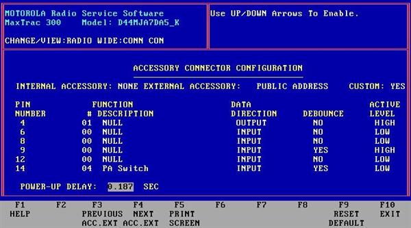 |
The most common error that is made is having the emergency switch enabled, which gives you an extra "boop" sound after the power up beep if you don't have the jumper on the accessory plug to disable it.
Now that you have those settings where you want them you can hit F10 to back up to the Change/View screen again. Hit F5 for mode configuration. You will only have one mode if you recently blanked and reinitialized the radio. Hit the F8 to go to mode utility and add as many modes (channels) as you need, up to the amount your radio is capable of. This is all self explanatory and pictures are not needed. If you have ever programmed a Maxtrac, or attempted to before, you should know how to get to the mode configuration screen.
Now let's put some frequencies in there for testing. You will want to program simplex channels starting at 440 MHz and ending with 450 MHz. Program #1 to 440.0, #2 to 441.0, #3 to 442.0, and so forth up to #10 at 449.0 and #11 at 450.0 MHz. These test frequencies are needed to calibrate the VCO steering line voltage. This is the easiest way, in my opinion, to move the VCO with nothing more than a voltmeter and a bit of patience. As discussed above, use the shift key method to enter the out of band frequencies below 449 MHz. Or you can hex edit the MAXTRAC.MDF or RADMBL.MDF file to change the "449" to "440". Hex editing is beyond the scope of this article, but directions can be found on the web. If you do, just make sure that you maintain / rebuild the checksum.
Now you need to disassemble the radio, and here is where you will need T10 and T15 Torx drivers. Remove the two flat-head T10 screws on each side, and the two T15 screws holding on the front panel. Pull the front panel out slightly and remove the top plastic cover. Remove the large shield on the top side of the radio (watch for a paper label to fall out and DON'T lose it), then the smaller shield below that. With the front of the radio facing you, you should see a point labeled SL under the area where you removed the smaller shield as shown in the picture below. (Click on the photo to see a larger image.)

This is the point you will use to monitor the Steering Line (SL) voltage while making VCO adjustments. When locked on a frequency you will generally see between 2-7 volts at this point. You can use the chassis as a ground point for the VOM. Now you see why I program the test channels.
While monitoring the voltage on SL put the radio on channel 1, 440 MHz. If the monitored voltage is below 2 volts simply adjust the Receive VCO coil (pointed to in the picture above) to bring it to or slightly above 2 volts.
Remember this, if you use a metallic tuning tool to make the adjustment it you must remove the screwdriver and check the voltage each time you adjust (the metal tool will detune it slightly). If you have a plastic coil adjustment tool that's much better, but not needed if you take your time and use patience in checking with each small adjustment.
Note
from WA1MIK:
the tip
of a wood or plastic toothpick can be flattened with
a pair of pliers. It will then fit into the square
metal
core of the VCO coils. Since it's not made of
metal, it will have no effect on the tuning, so you
can
measure
the SL voltage with the tool in place.
Repeat this process through all the test channels up to 450 MHz. The goal is to keep the SL voltage within the workable 2 to 7 volt range throughout the entire 440.0 to 450.0 MHz range. You only have to verify and adjust the voltage by using the lowest frequency you will be using, but, you should also double check the voltage across the rest of the test frequencies to assure its stability. You should see a gradual climb in voltage as you change channels upward. When the SL reading gets past 7 to 8 volts you reached the highest frequency it will now reliably operate on.
The next step is to do the same for the transmit side. To do this connect the radio to a dummy load, and connect a microphone; keep the transmissions short with pauses of equal or longer times in-between to allow cooling of the PA. I put a muffin fan by the PA heat sink to speed up cooling while testing. Above all else, take your time and have patience! If you plan on doing this often enough it's worth building a simple PTT footswitch, I use a cheap footswitch with a RJ-45 plug installed for the mic jack. This allows you to have both hands free to monitor SL and adjust the coil.
Note
from WA6ILQ:
Thrift
stores get old Dictaphone machines in from time to
time. They have very nice and sturdy
footswitches... Some of them even have multiple
switches (for some combination of rewind, stop, play
and
fast
forward, depending on the model) and you can wire
one of them to PTT, and use the other switches for
whatever
you want... a carrier/PL mode change or...
To adjust the TX VCO monitor the SL voltage while transmitting, starting again at 440.0 MHz then checking the remaining test channels. Adjust the Transmit VCO coil (pointed to in the picture above) to keep the SL monitored voltage between 2 to 7 volts for TX.
If the coil has been adjusted to a higher frequency previously you may notice that the lowest frequency, 440 MHz in this case, will not allow the radio to transmit for more than a second or less when you push the PTT, or the TX / Busy light will not even come on when PTT is pressed if the SL voltage is too far off. This is NORMAL; it will start to transmit fully when you get the SL voltage above or near 2 volts. Sometimes the radio will operate out of the 2 to 7 volt range. It's more of a guideline reference voltage than an absolute must, but if you're out of the 2 to 7 volt range you will have reliability problems with your mobile radio when the weather changes. It may unlock when cold, and return to working when it warms up. By the way, if the radio powers up with a continuous series of beeps this means that the RX VCO is out of lock.
The only other concern is TX power output calibration. For this you simply need a good quality wattmeter and the RSS.
Go to the main menu, select F2 for the Service Menu, F6 for the Board Replacement Menu, then F2 for the Logic Board or RF Board Menu.
The one you want on this screen is F5, but the software will not allow you to select the screens out of order. So select F2, then exit back with F10, and repeat for F3, and F4, and finally you can get to the F5 Set TX Power Calibration. The RSS has it's own set of test frequencies here. Make sure the radio is hooked up to the wattmeter and a dummy load and then press F6 to turn on the transmitter, check the wattmeter, then press F6 again to turn transmit off. The default values for 1-5 are usually in the 80's were not calibrated on most radios since these test frequencies cover the ham band.
If the transmit power was low increase the number and try again, if it was high then decrease the number and try again. When you turn the transmit on it will display what frequency it is transmitting at bottom middle of the screen. As with the VCO adjustments keep the transmissions short with rest times in-between to prevent overheating the PA. A couple of the radios that I worked on would not go above 35w, while others might go the full 40w, and at least one person reported to me that the most they got at number one is 30w. After adjusting number one hit return to go to number two. Do this until you have checked all sixteen test frequencies or you hit the highest one at which the VCO will now operate, remember you realigned the entire VCO range downwards, so just as you would expect at some point the upper test frequencies will no longer lock and the radio will not transmit. So don't be surprised when you get above a certain point that the TX / Busy light only flickers or the radio doesn't transmit at all.
After you're done on this page hit F8 to program the values to the radio then F10 to exit out to the main menu. You may want to save your codeplug file that has the 440.0-450.0 test frequencies for when you have to work on the next radio. Once that is done, you can program the actual frequencies that you wish the radio to operate on. Don't forget to save the new codeplug data, and perhaps even backup the codeplug when you're done programming the radio and before exiting the RSS.
A big THANK YOU to Bob Meister WA1MIK for a high quality photo of the RF board.