The TTL Digital Clock
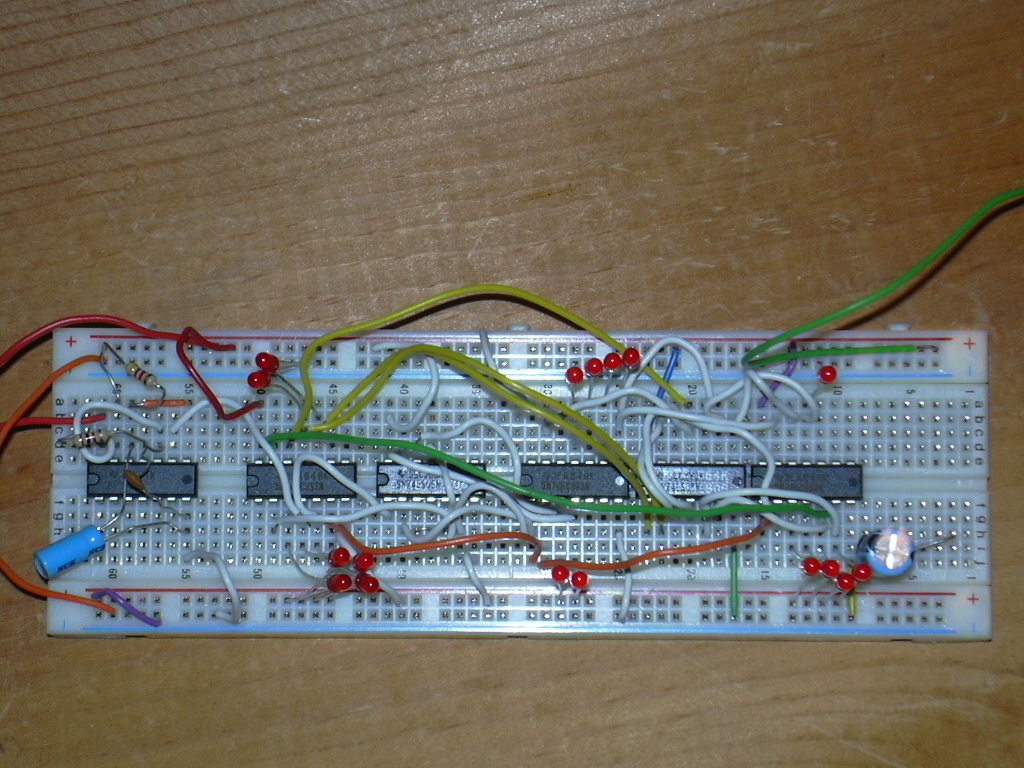
Digital Logic was one of my classes during the Spring 2007 semester, which motivated me to build a TTL level discrete circuit digital clock. The design is a simple binary clock, read out on LED's. The integrated circuits were purchased at Fry's Electronics and Radio Shack and assembled on a breadboard I had lying around. For specifics, just look at the schematic and block diagrams below.
The 555(556CN) timer is implemented in astable mode, with the components set to pulse
approximately once per second. (Little effort was expended in accuracy for this
proof-of-concept experiment.) Its period can be determined by:
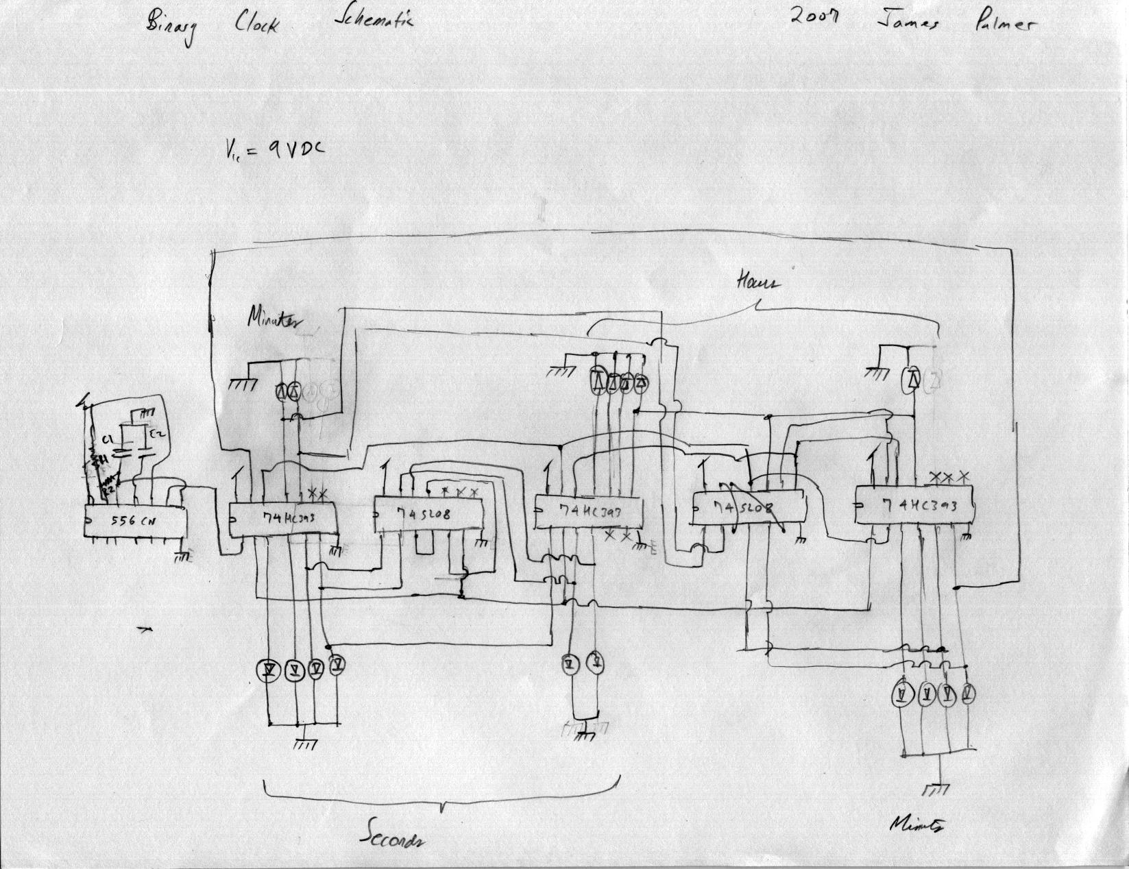
T = .7 x (R1 + 2*R2) x C1
(taken from here)
If you can't read the schematic very well, R1 is vertical, and R2 is horizontal.
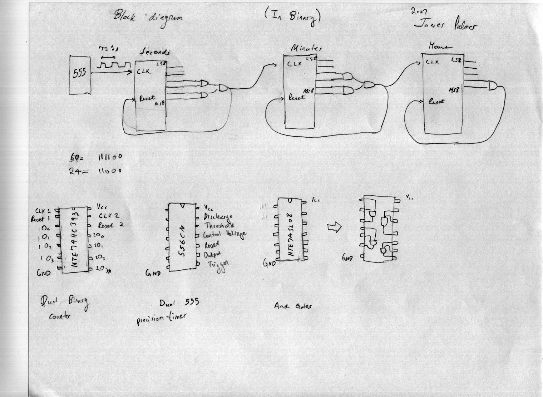
The timer feed a cascade of binary counters, the first and second resetting after 60 counts, and
the last after 24 counts. A set of AND gates applies the resetting potential to the
counters, in the guise of a finite-state machine.
Digital clocks don't get any simpler than this, so I encourage you to try it for
yourself. Have at it!
end of line.