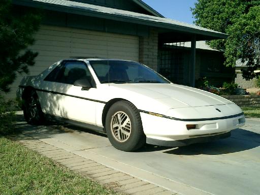
| Motor: |
Prestolite MTC-4001, Series Wound, Rated 20 HP @ 96Volt |
| Drivetrain: |
Original 5 speed (Isuzu) Transaxle with a heavy duty clutch and the ring gear removed from the flywheel in order to lower the rotating mass |
| Controller: | Auburn Scientific Kodiak PWC-600 (water cooled using the windshield washer fluid) 72-144V, 680A Mosfet 15Khz PWM controller) mounted in the "tunnel" where the fuel tank was formerly located. |
| Batteries: | 20 Saft STM5-180 flooded NiCd, 6 in the front, 14 in the rear in the "engine compartment" connected in series. These are 6 volt, flooded, golf cart size batteries salvaged from a San Diego city bus and were chosen for their longevity. (20+ years) |
| System Voltage: |
120 Volts nominal |
| Available Power: | 21600 Watt Hours (More than enough to run all the equipmment for a sizeable Field Day operation.) |
| Charging Equipment: |
Russco 180-18 SO on-board enables charging from any 120V outlet.
Modified Bycan 12/108-25
Also have a "Fronkensteen" 0-144V, 10A charger made from two 36V golf cart chargers that I seperated the secondaries and reconnected them in series for 144V, then added a Variac, timer, meters and cooling fans along with wheels! |
| Heater: |
I have a ceramic element that will eventually be installed but heat is not high on the priority list here in Phoenix. |
| AC: |
Presently working on coupling the original V-5 compressor directly to a 120V, 1.75Hp treadmill motor and controlling it from the stock dash controls. (All of the original AC system is still in place except the compressor.) |
| 12V Accy/Lights: | 17 AH sealed lead acid battery with an Iota DLS-30 switch mode battery charger that is "ON" when in Run mode, much like the alternator in an ICE vehicls. (Originally intended for motor home battery charging). Switch mode power supplies or chargers work very well with a DC input and some will function with a nominal 120 Volt DC supply. This keeps the small 12V battery charged from the main pack and provides the low voltage for lights, wipers, horn, fans and relays. |
| Instrumentation: |
Rally guages modified to read battery pack voltage and current |
| Top Speed: |
75+ |
| Range: |
Proven 60 Miles. |
| Seating Capacity: |
2 adults |
| Additional Notes: |
Power brakes with a 12V Delco vacumn pump
Instrument panel indicator lights rewired to show "pre-charge" & "Ready".
Controller Pre-Charge circuit uses a 120 VDC adjustable Time Delay Relay and a 130V, 90W traffic signal lamp. (Thanks to Lee Hart for the circuit and KA7IOG for the traffic light bulb.)
Yeasu FT857d with an AT120 antenna.
Pack temperature sensor & vehicle interior temp.
My first attempt to install a dual band 2 meter/440 antenna was a learning experience. Because the Fiero body panels are constructed from FRP, or Fiberglass Reinforced Plastic, there really is no Faraday cage to keep RFI out of the electronics. The Fiero has a metal plate under the rear, or engine, deck lid. I assumed this was to keep the RFI out of the Engine Control Module.. the engine computer. I installed a j-shaped piece of sheet metal at the front edge of the deck lid to support the antenna.
The first day using this setup I pulled away from a traffic light and being engaged in a conversation with another ham, I keyed up to take my turn in the morning "ride to work" net. The engine faltered and the "Check Engine" light came on. I immediatly unkeyed, the engine smoothed out and I cleared the intersection. Further tests revealed that this was not the place for the antenna as the metal shield did NOT keep RFI out of the ECM.
While I could operate on low power with this placement, I elected to move the antenna to the side of the passenger side engine air vent in order to be able to make the repeater from the fringe area's. |


 [email protected]