Antenna Tracking Systems
-2m Dish For Amateur use-
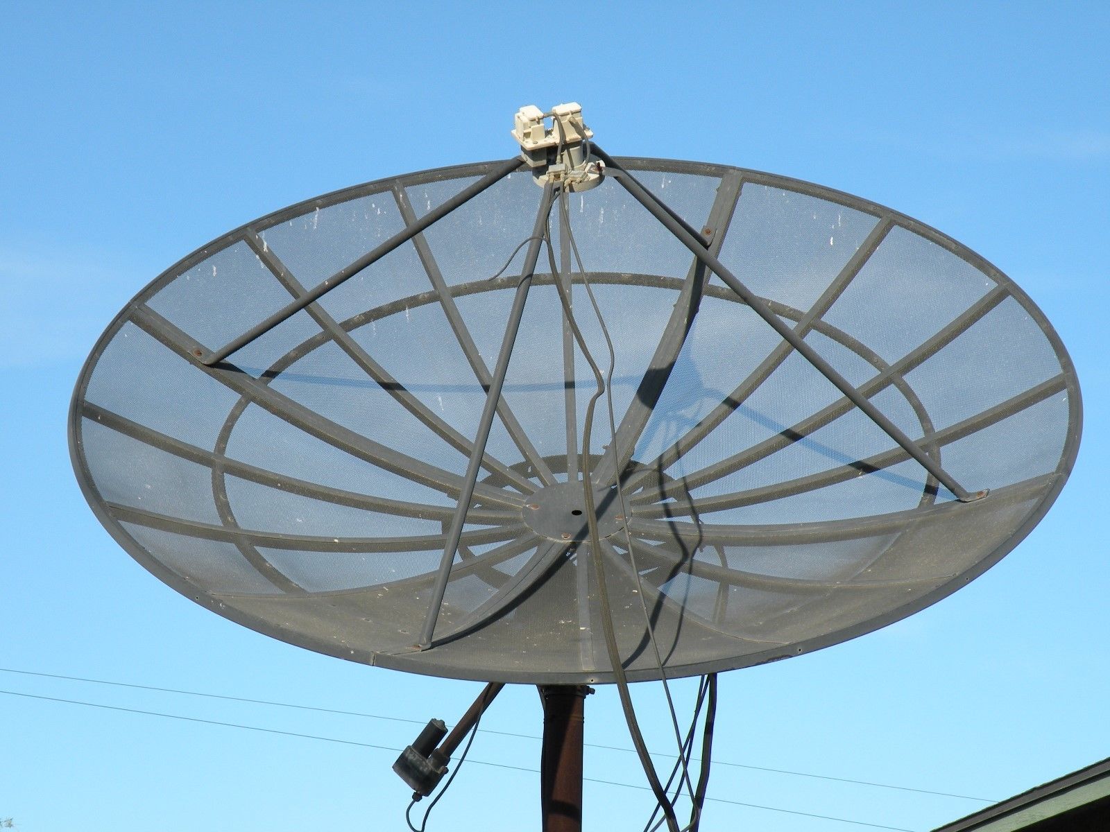
This project hopes to identify what use a 2m C-Band dish has after being acquired by a ham. A little bit of history and background on GEO satellites and my perspective on what can be done with this type of mount and dish.
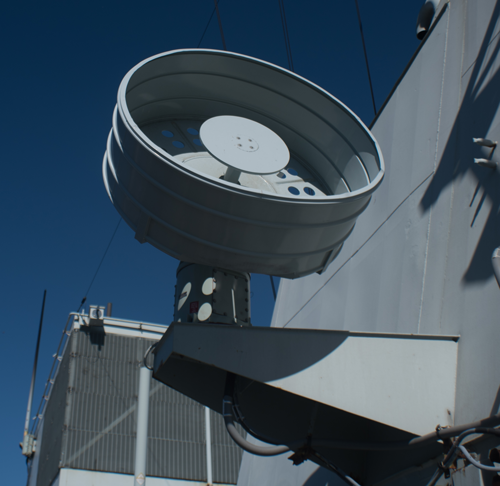
(Dish as it was when it was claimed for $25)
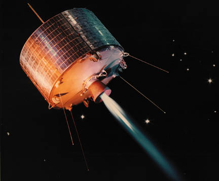
The history of geosynchronous satellite communication started with Syncom-1 the first geosynchronous satellite, on Feb. 14, 1963 and then Syncom II that would transmitted live coverage of the 1964 Tokyo Olympic games to North America and Europe. geosynchronous satellite comunications has evolved into much more!
I'm not chasing DX just GEO communication signals.
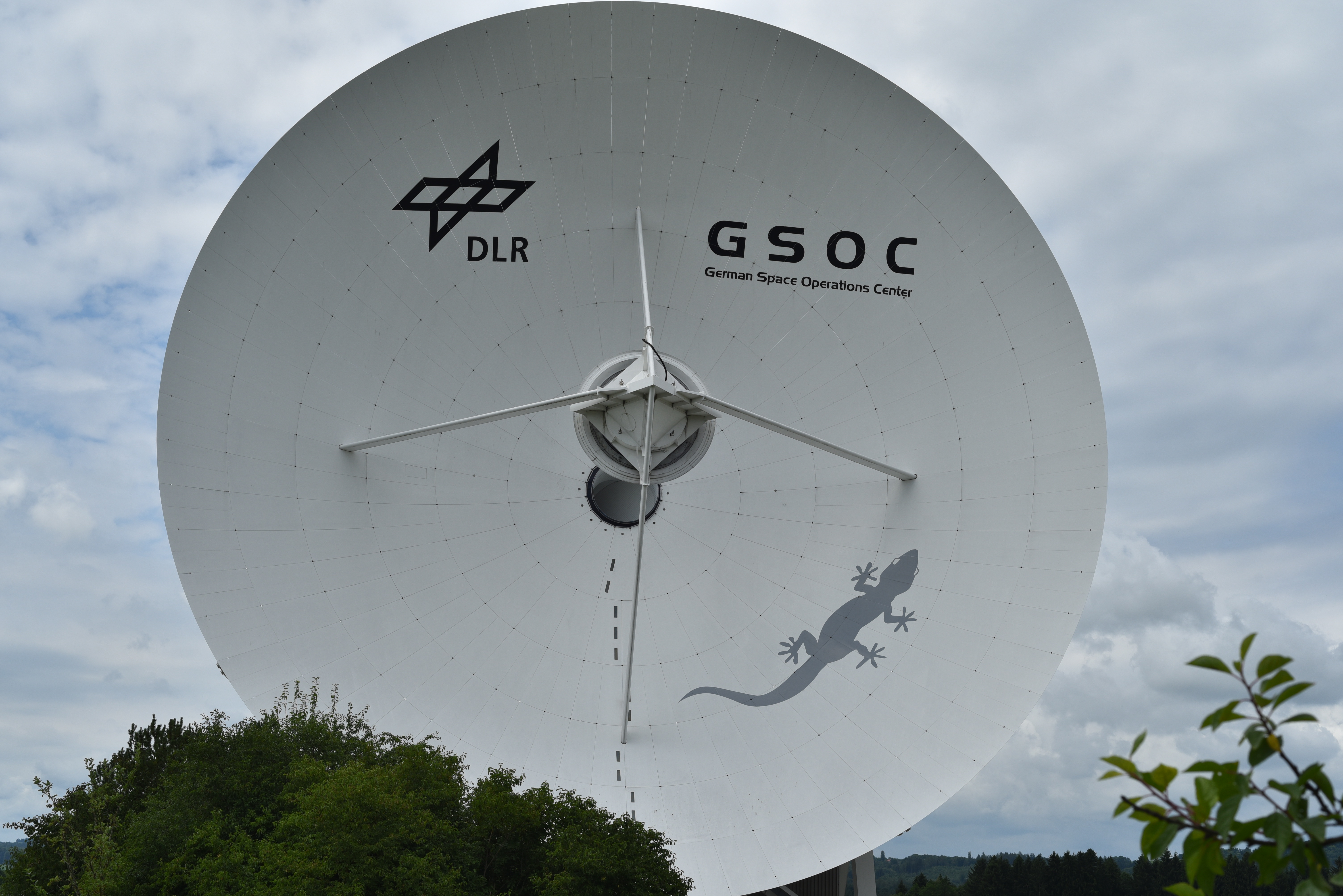
DLR space network Dish at V3JJ+77 Wielenbach, Germany.
The Deep Space Network & An account of space comunication frequencies
Q;Will it be possible to work Amateur Radio stations from Geosynchronous Transponders?
A:Yes when they launch
Q:What other Man Made signals can be intercepted from GEO?
A;Lots of signals!
Q;How do I point this dish with only one motor?
A;The restricted movment dose track an arc in the sky, and Im going to need some equipment and a new mount.
Q;What sort of gain dose a 2m dish have relative to the band plans of possible signals?
A;its not a 35m dish but it dose have gain!....
Q;Would it be possible to work the EME Earth-Moon-Earth with a 2m dish?
A; Well... maybe @ 10ghz
HERE WE GO!
Thanks to the FCC for Amateur allocations with in this spectrum and band plans exist. We don't need a license to receive signals.
| Band | Frequency Range | Origin of Name | FCC Rules, Part 97.301(a): |
|---|---|---|---|
| I | up to 200 MHz | Unknown | |
| G | 200 to 250 MHz | Unknown | |
| P | 250 to 500 MHz | P for "previous", as the British used the band for the earliest radars, but later switched to higher frequencies. | Pband applications |
| L | 0.5 to 1.5 GHz | L for "long" wave. | 1240-1300 MHz: CW, Phone, Image, MCW, RTTY/Data |
| S | 2 to 4 GHz | S for "short" wave. Don't confuse this with the short wave radio band, which is much lower in frequency | 2300-2310 MHz /2390-2450 MHz / 3300-3500 MHz |
| C | 4 to 8 GHz | C for "compromise" between S and X band. | 5650-5925 MHz |
| X | 8 to 12 GHz | Used in WW II for fire control, X for cross (as in crosshair) | 10.0-10.5 GHz |
| Ku | 12 to 18 GHz | Ku for "kurz-under". | |
| K | 18 to 26 GHz | German "kurz" means short, yet another reference to short wavelength. | 24.0-24.25 GHz |
| Ka | 26 to 4-0 | Ka for "kurz-above". | |
| V | 40 to 75 GHz | V for "very" high frequency band (not to be confused with VHF) | 47.0-47.2 GHz |
| W | 75 to 110 GHz | W follows V in the alphabet | 76.0-81.0 GHz |
source: https://www.microwaves101.com/encyclopedias/frequency-letter-bands
As of Sept 2018 AMSAT PHASE4 update...
https://phase4ground.github.io/index.html
The project looks to be delayed. But if your on the other side of earth there is Es'hail 2 with: X-Band 10 GHz Down-link / S-Band 2.4 GHz WB-Uplink. is looking at a late 2018 flight! update 8/2018
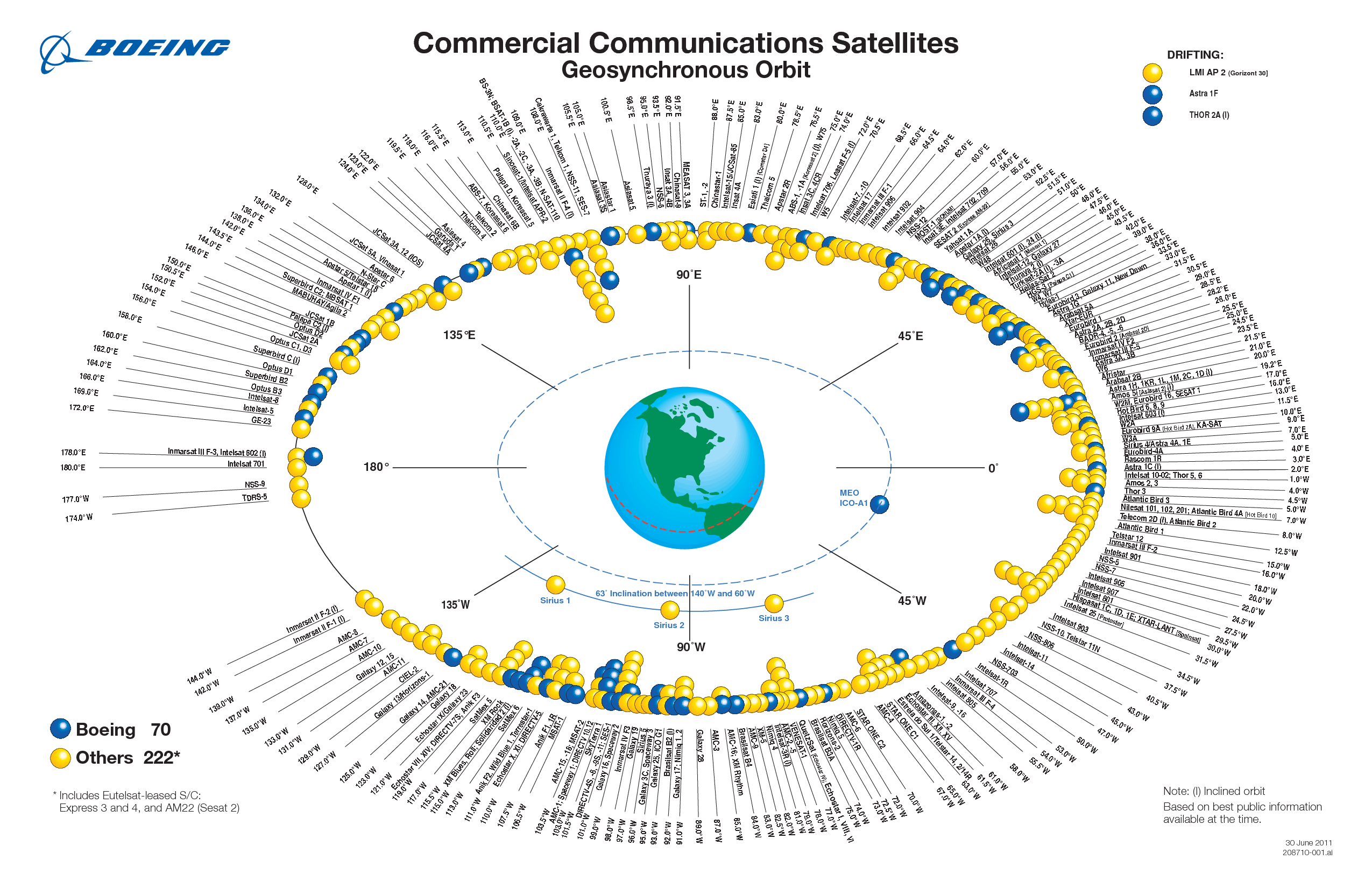
Operational transponders on the Ham bands will open up a whole new set of operational activities. I hope that once the projects launch I can work on an unlink and down-link chains. In the mean time what type of signals can be received with an Earth station, and what methods can be used to track, and capture signals? Most GEO satellites don't move much and most fall on an arc from east to west.
For refrence here an example ground station layout for Phase4.

The dish was originally intended to receive C band FTA transponder signals from GEO. What bands do most GEO satellites operate on?
Signals to investigate...
NOTE: NOT to scale!!!!!!
![]()
Othernet aka Outernet is a Ku band data down-link formally available @ 1.2ghz L-band, as of September 2018 they have moved operations to a Ku band transponder on SES-2.
https://cdn.shopify.com/s/files/1/0770/0935/files/Dreamcatcher_V_3.03_User_Manual.pdf
https://en.wikipedia.org/wiki/Outernet
Sat-Com signals tend to be military, that of witch I'm not interested in at the moment. Satlites support FM on the 200mhz band others are digital. Here is a good list of Birds. This guy, keeps andl ogs intercepted Sat-com transmissions on a blog. Ez enough to demodulate and Ez for hoodlums to pirate and hackers to reverse engineer the protocols! ENJOY!
http://www.iicybersecurity.com/intercept-satellite-communications.html

FTA " Free To Air" TV signals, most people know about Dish-TV or Direct TV well this is free HD/SD video. Most of the FTA stations are on C and Ku band transponder and available based on the geographic coverage of the Satellite's antennas. Satellite transponders carry some open and encrypted/payToview DVB-S2 video. The most common way to decode the signals is with FTA set top box decoding DVB-S/ S2 and DISEQC commands for LNB (I will detail this later) There is a Linux OS project called openpctv that supports DVB and ATSC card on the market. There are a few tools to @ http://dvbsnoop.sourceforge.net/ that run on Windows and a Android. Alternatively GNU Radio has adopted DVB-S/S2/S2X blocks into the standard Gnu Radio. There are some possible limits to using SDR's identified by R.X. Seger in his blog about decoding ATSC signals.
--Help finding Satalites--
http://www.highspeedsat.com/geostationary-satellites.php
http://www.ftalist.com/master.html
~~The Tracking and Control System~~
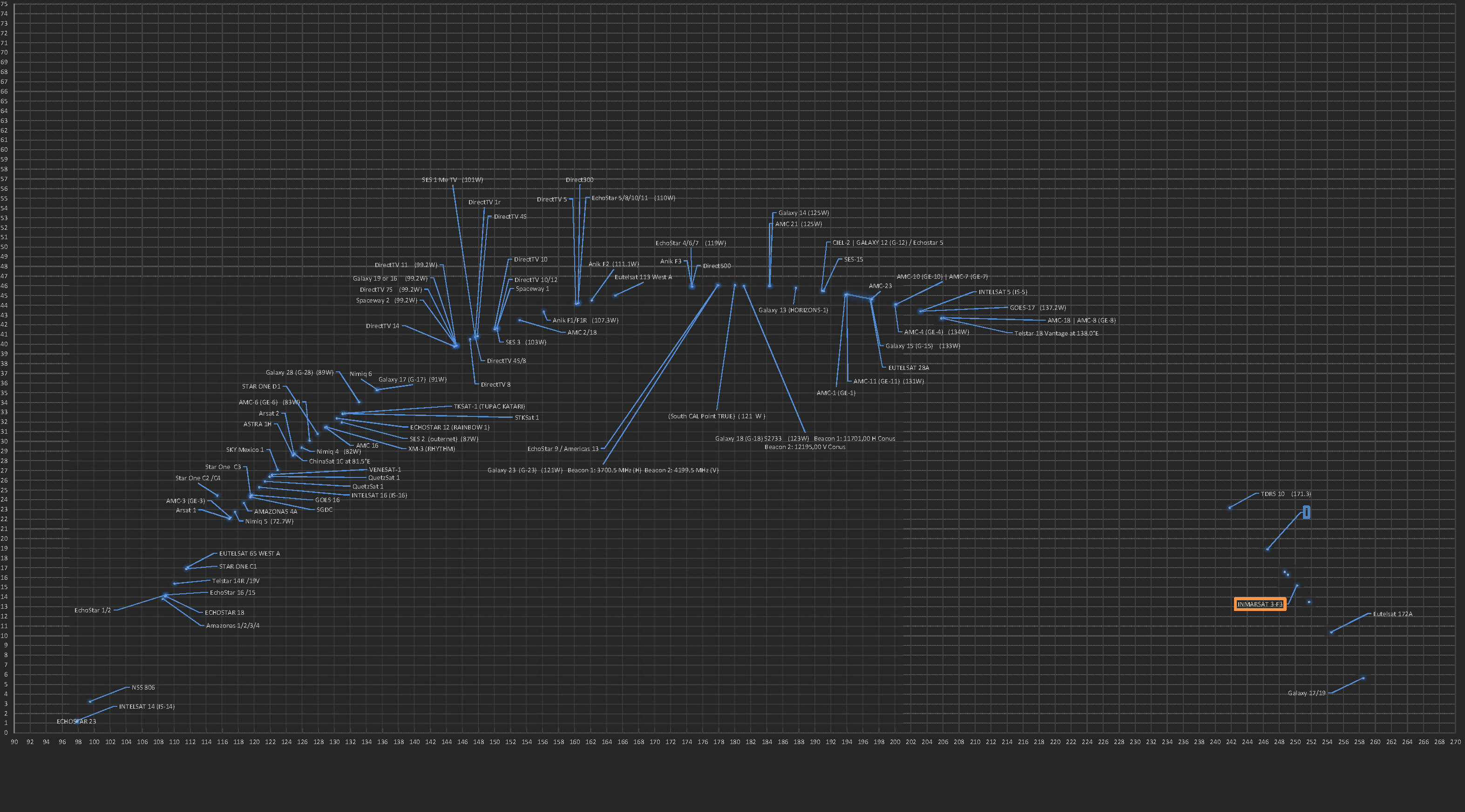
Most GEO satellites don't deviate from an arc from east to west in our visible sky. Ive created this image from data sets I use to keep track of satellites in my field of view @ CM87uv. I will continue to plot visible satellites and possible obstructions in my FOV. It's going to grow...
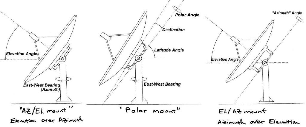
For all intensive purpose with this mount I'm only going to be able to point dish at GEO satellites along 1 axis of control. The Moon and LEO satellite tracking needed at least 2 axis of movement. At the moment this dish is on a polar mount. Polar mount (Left) & AZ / EL (Right)
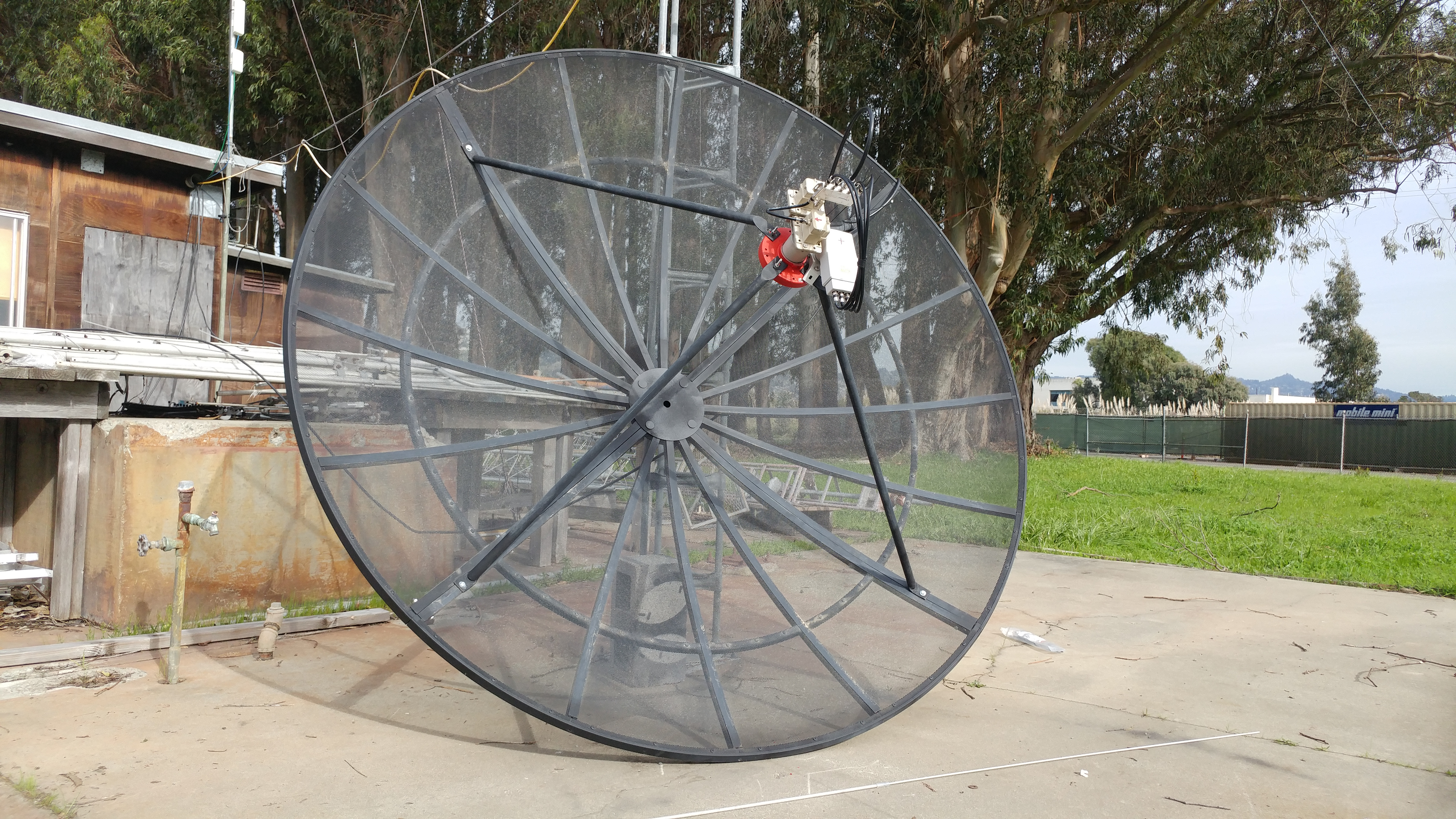
A motorized mount will alow the dishe to track along it's field of view for signals. Care must be taken to mechanically calibrated the mount before the dish will track properly.
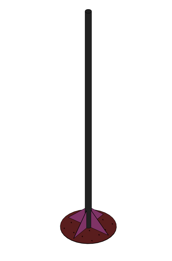
My base place took about 5hr to prep the steel for weld of the base. Drilling holes in the plate and concrete for concrete bolts to tie it down to the concrete pad at our station.
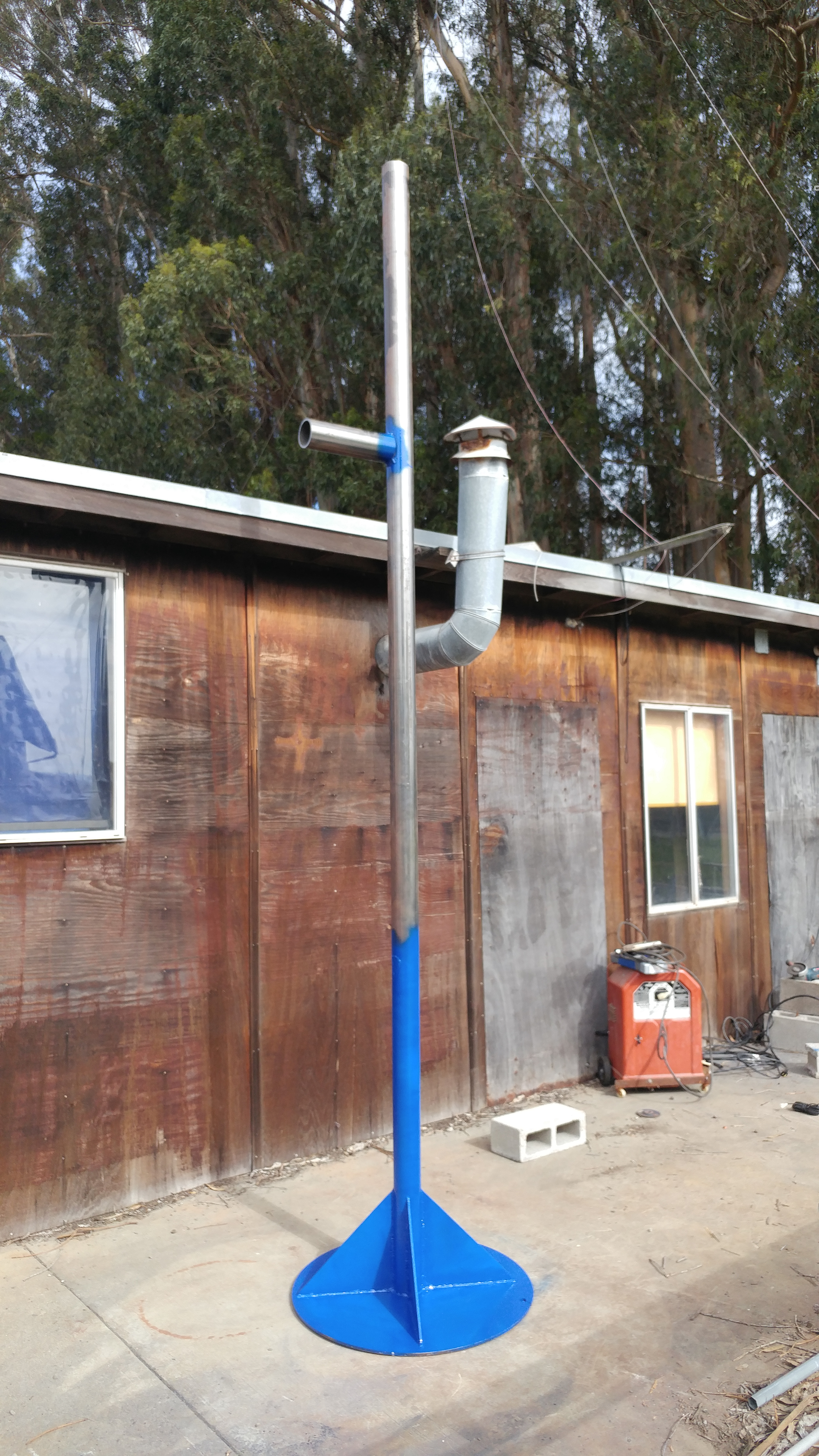
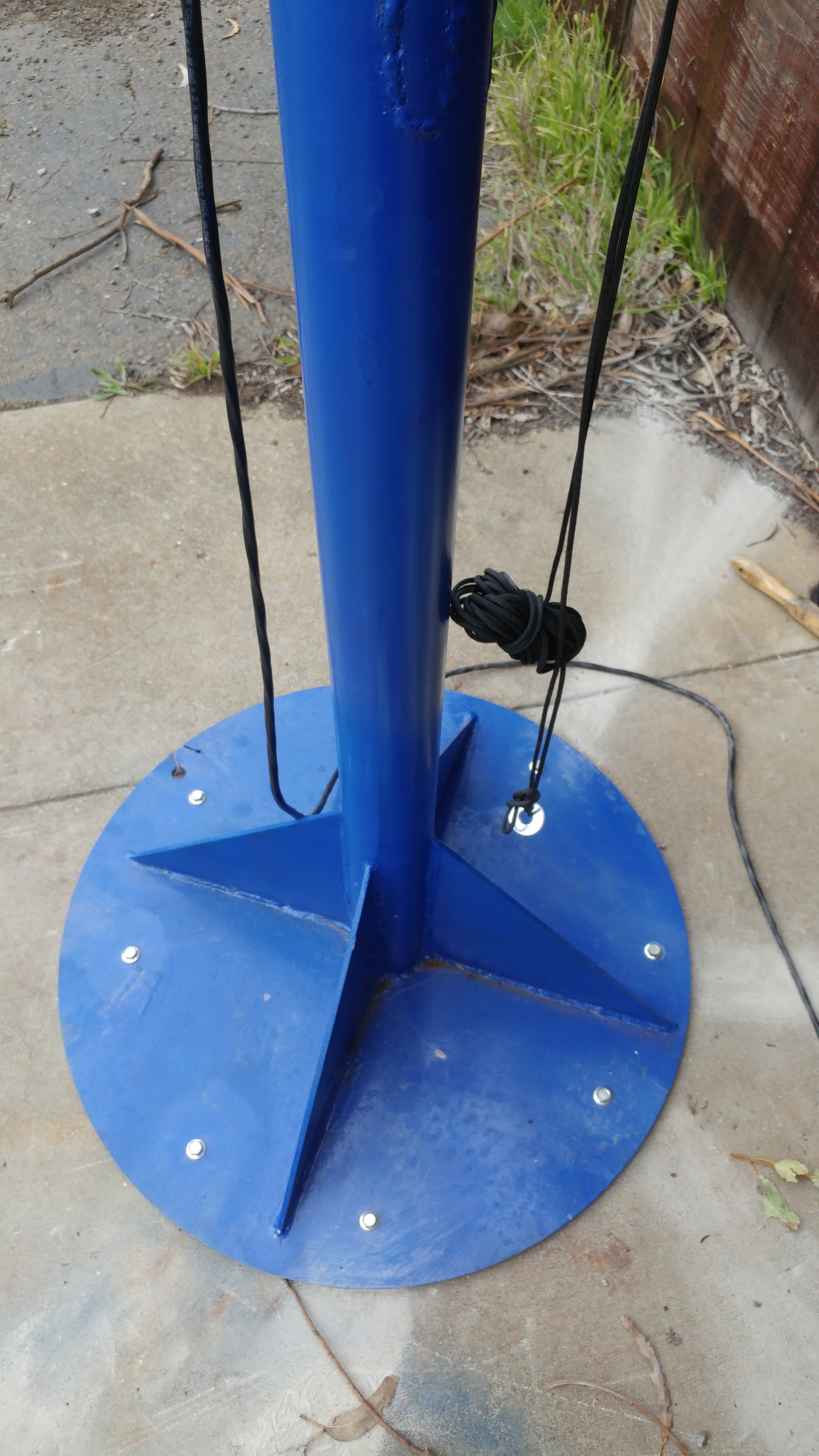
That's done NOW on to setting up the dish!
With KISS in mind... I chose not to use an arduino based system.
Ive chosen to use the 2 axis Arduino based antenna controller project as a single axis control loop. If only I had this project back 2007 when I started the antenna tracking head!
Throw some buttons, a relay board, DC speed controller ,supported LCD, a potentiometer and power supply together with an Arduino and you can have a controller.
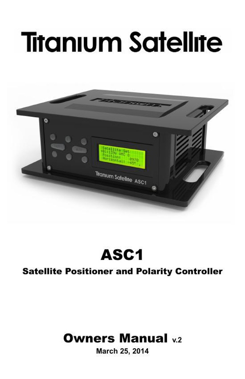
The Titanium ASC1 DiSEqC Positioner Satellite Motor & Polarity Controller is to me the only modern off the shelf option available to control the polar mount.
Here is a good article about the device. file

Calibrating a polar mounted Dish! http:///FTAMOTORINSTALL.htm
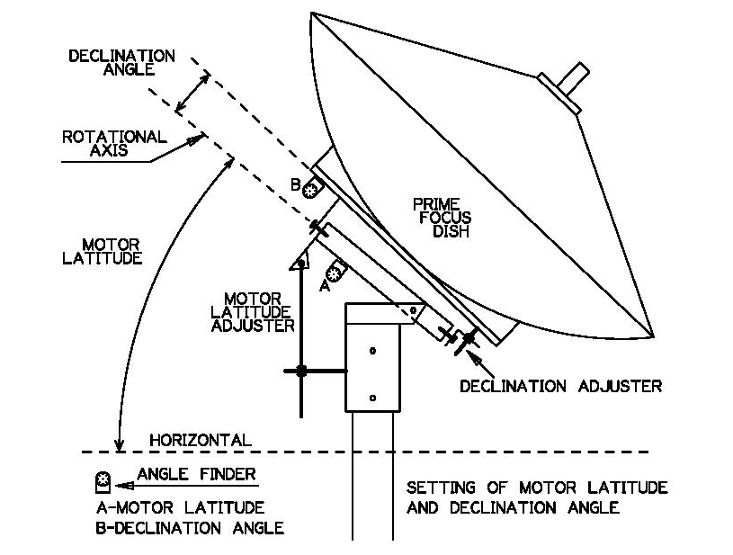
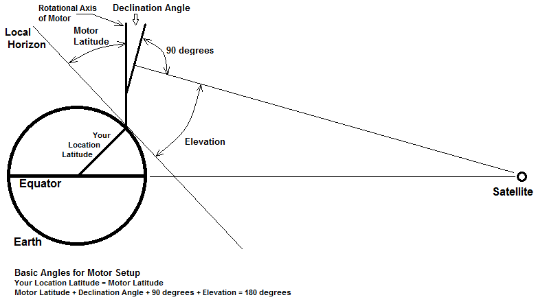
Ive found 2 diffrent calibration figures!?
(Motor Latitude angle = 38.6) (Declination angle= 5.3) (Motor sideways angle= 1.5)
(Motor Latitude angle = 36.69) (Declination angle 5.09) (Zenith 41.78)
Its time to get to work seeting the angles on the bracket and Refinement as need againt signals.
Source of declination tables : http://www.bigdish.info/mainten/align.html
DISEQC WHAT? "Digital Satellite Equipment Control"

Its a bit code modulated on a 22khz square sine wave is transmitted up the recevers coax to devices. This command system alows multible LNB/ antennas to be selected within a DISEQC switch as well as motor position to be sent to deveices. It gets a little complicated so read the spec. DiSEqC WIKI FTA receiver boxes employ this comand protocal.
RPI basesed generator for DiSEqC comands.
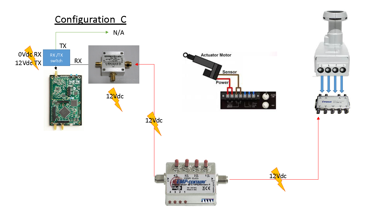
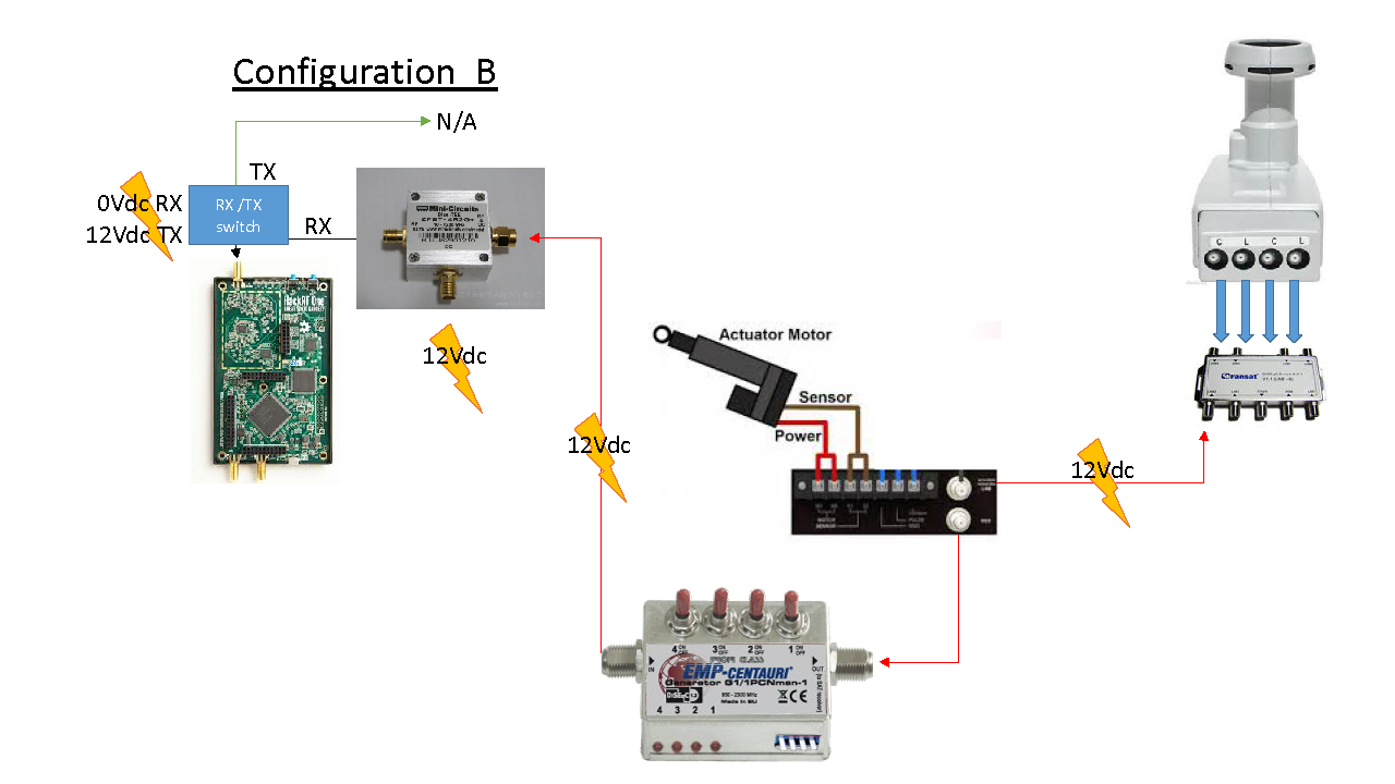
Below ive inclded a few system diagrams, to emphasize a few diffrent ways that I can configure my station.
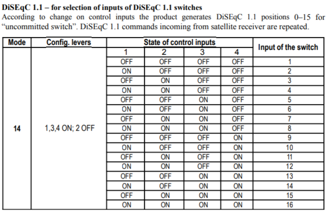
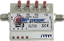
First I knew I would need to generate DiSEqC switching comands so I picked up a : 1 x 8 DiSEqC 1.1 switch and a EMP-Centauri Generator G1_1PCNman-1 P.115.
The G1-1PCN will generate commands for a 8 x 1 switch and if I run the G1-1PCN in mode 14 as above it will switch between the 8 inputs. The ASC1 can work standalone to control the polar mount altho I would like to move the antenna remotly in the future. A FTA set-top box will help to validate LNA switching and FTA signal reception. The G1-1PCN dosn't generate DiSEqC's GoTo commands and I loose .5dbi of signal if I pass thou the ASC1. I dont need the ASC1 to in line to receve DiSEqC postion comands from the FTA box. A hackRF sits on the loop output of the FTA box, caution has to be taken to isolated the device from DC that could be on the line. 12volts could be present on the loop and I don't plan to burn up another hackRF from 12volts (Shure's distributed antenna !!!)
LNB's require bias-tee incertion of 12Vdc to power switches, small motors, and LNB's. Some LNBs switch between H/V when the voltage 12Vdc to 18Vdc, Ive chosen units that breakout indivigual H/V/LHCP/RHCP circuts to a DiSEqC switch.
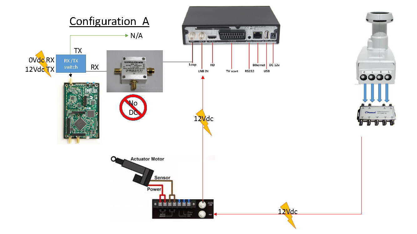
Now I can switch between diffrent recever channels with an insertion Loss of 3 dB on a 950-2150 MHz DiSEqC switch.
1 : Cband H pol
2 : Cband V pol
3: Ku H pol (11.7 – 12.2 GHz)
4: Ku V pol (11.7 – 12.2 GHz)
5: Ku LHCP (12.2 – 12.7GHz)
6: Ku RHCP (12.2 – 12.7GHz)
7: N/A
8: N/A
Low Noise Block Down-Converters receive 12ghz Ku and or 4ghz C band and down convert baseband to between 950Mhz and 1450 MHz. Down-converted baseband can be receved with an every day scanner or SDR receiver.
| Band | Frequency Range | Origin of Name | FCC Rules, Part 97.301(a): |
|---|---|---|---|
| I | up to 200 MHz | Unknown | |
| G | 200 to 250 MHz | Unknown | |
| P | 250 to 500 MHz | P for "previous", as the British used the band for the earliest radars, but later switched to higher frequencies. | Pband applications |
| L | 0.5 to 1.5 GHz | L for "long" wave. | 1240-1300 MHz: CW, Phone, Image, MCW, RTTY/Data |
| S | 2 to 4 GHz | S for "short" wave. Don't confuse this with the short wave radio band, which is much lower in frequency | 2300-2310 MHz /2390-2450 MHz / 3300-3500 MHz |
| C | 4 to 8 GHz | C for "compromise" between S and X band. | 5650-5925 MHz |
| X | 8 to 12 GHz | Used in WW II for fire control, X for cross (as in crosshair) | 10.0-10.5 GHz |
| Ku | 12 to 18 GHz | Ku for "kurz-under". | |
| K | 18 to 26 GHz | German "kurz" means short, yet another reference to short wavelength. | 24.0-24.25 GHz |
| Ka | 26 to 4-0 | Ka for "kurz-above". | |
| V | 40 to 75 GHz | V for "very" high frequency band (not to be confused with VHF) | 47.0-47.2 GHz |
| W | 75 to 110 GHz | W follows V in the alphabet | 76.0-81.0 GHz |
source: https://www.microwaves101.com/encyclopedias/frequency-letter-bands
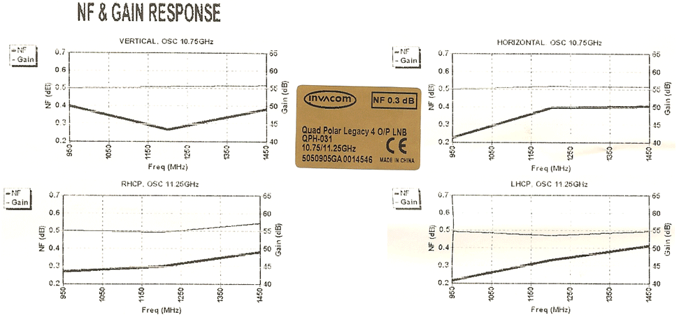
The QPH 031 Quad Polar LNB is quite excellent for Ku and upper X band, I'm glad I purchased one!
DVB-S2X in GNU Radio
The DATV group has built a number of boards https://www.datv-express.com/ the new LimeSDR is a new platform for the project. they focus on digital terrestrial Amateur TV "DATV"
https://limemicro.com/products/
https://hackaday.com/tag/limesdr-mini/
Wiki list of current SDR on the market
~~~~~~~~~~~~~~~~~~~~~~~~~~~~~~~~~~~~~~~~~~~~~~~~~~~~~~~~~~~~~~~~~~~~~~~~~~
MOOOOOOOOOOON!
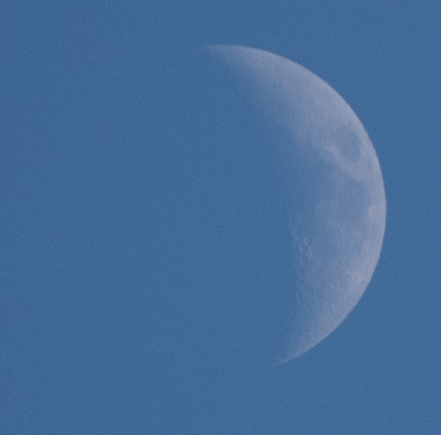
The first Amateur Lunar tests & contacts |1st part: 1953-1965
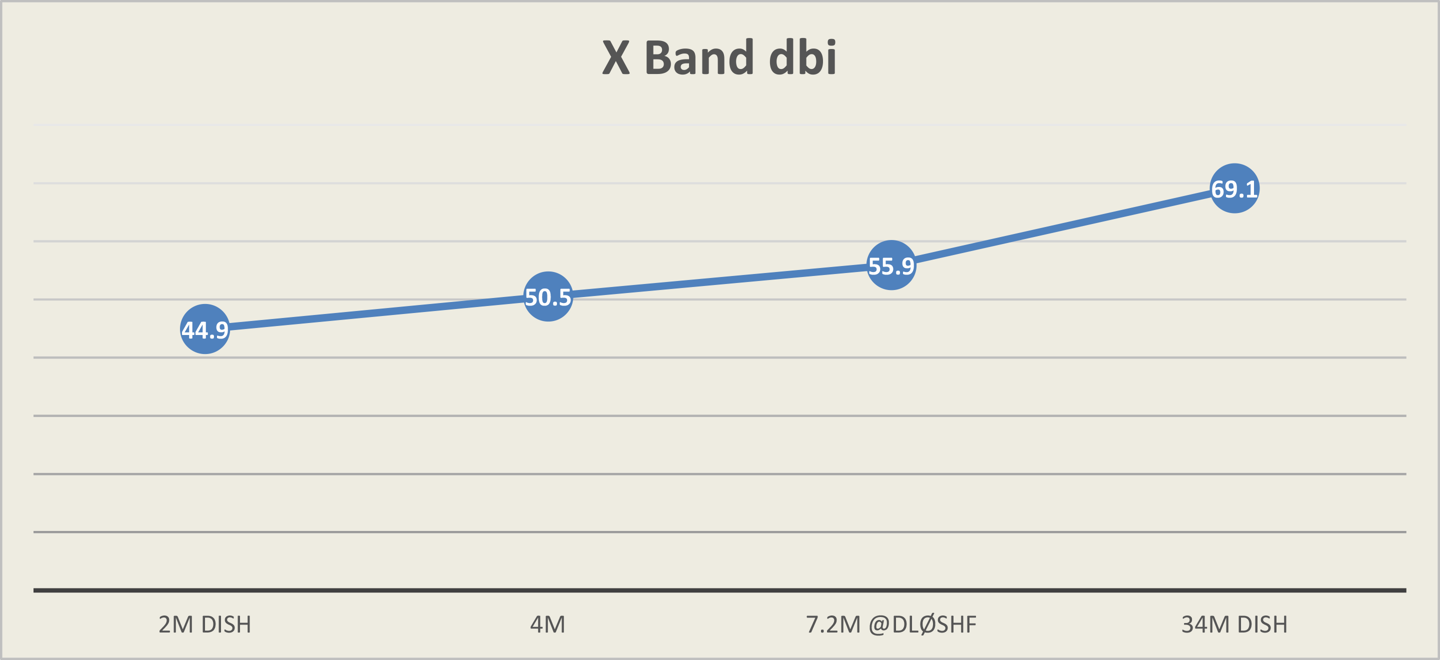
With the moon insight... It's a little out of reach for a 2m dish or is it??? It's my opinion the resolution of mechanical tacking system will need to step-up it 's resolution, and could even require a secondary control loop. Thats a topic for another day.... Joe DJ7FJ details the relation of dish size, gain, beam-with and noise using x band for EME. A 2m dish is a feasible option for X-Band EME because of the beam-with characteristics of a 2m dish. A 4m dish has it's advantages. Moon Becon
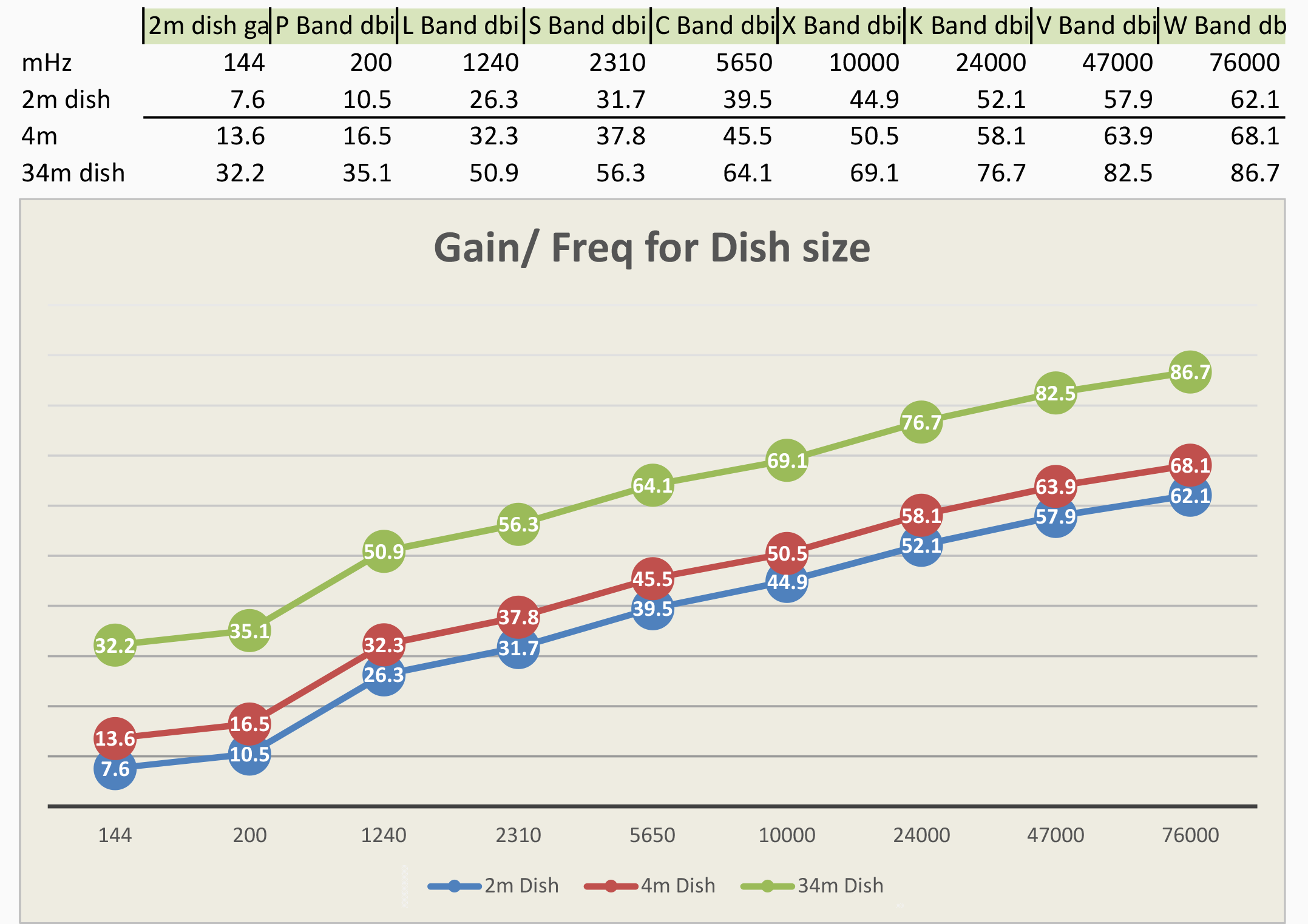
I've made a table to compares dish size vs. gain for different bands. This will help me refine the RX signal chain at this stage. In the future it could refine chains for Tx chain. While I don't plan to transmit with this system at the moment It's important to note that a 4m dish is a better option for Tx .The tables provide perspective on dish dimensions, LNA gain, horn gain, cable loss , switching loss, radio receive db . Exploring signal chains in relation to relative free space path loss & return margins @ different frequencies. Ive also found the information on antenna size and transponder power to reference path-loss between GEO satellite and an Earth station and path loss margins for [Earth----->Moon----->Earth]
What I'm up-against?
NOTE: To scale! [GEO] 35,786 km (22,240 miles) , [Moon] 384,000 km (238,607 miles)

NOTE: one of the factors I don't address in my numbers is the aperture of the dish. Why? well it has to do with the dimensions, specificity the dept of the a dish. The dept of a dish will effect the aperture dramatically. Large dishes can shift the secondary reflector to alter there beam-with to an extent (I haven't modeled this) I would suspect that by varying the dish's depth and focal point the beam-with should be adjustable. This could be explored with extensive antenna modeling. Its beyond the extent of what I'm trying to do. Parabolic Dish Focus, Zoom, and Tilt Paul Wade W1GHZ ©2009 writes about adjusting the feed position to alter beam-with.
Paul Wade N1BWT offer his prospective so back to the Basic principle of focal point
| Focal length = f
Depth = c Diameter = D f = ( D * D ) / ( 16 * c ) |
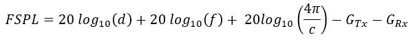
Free space path loss and don't forget to factor in reflection!
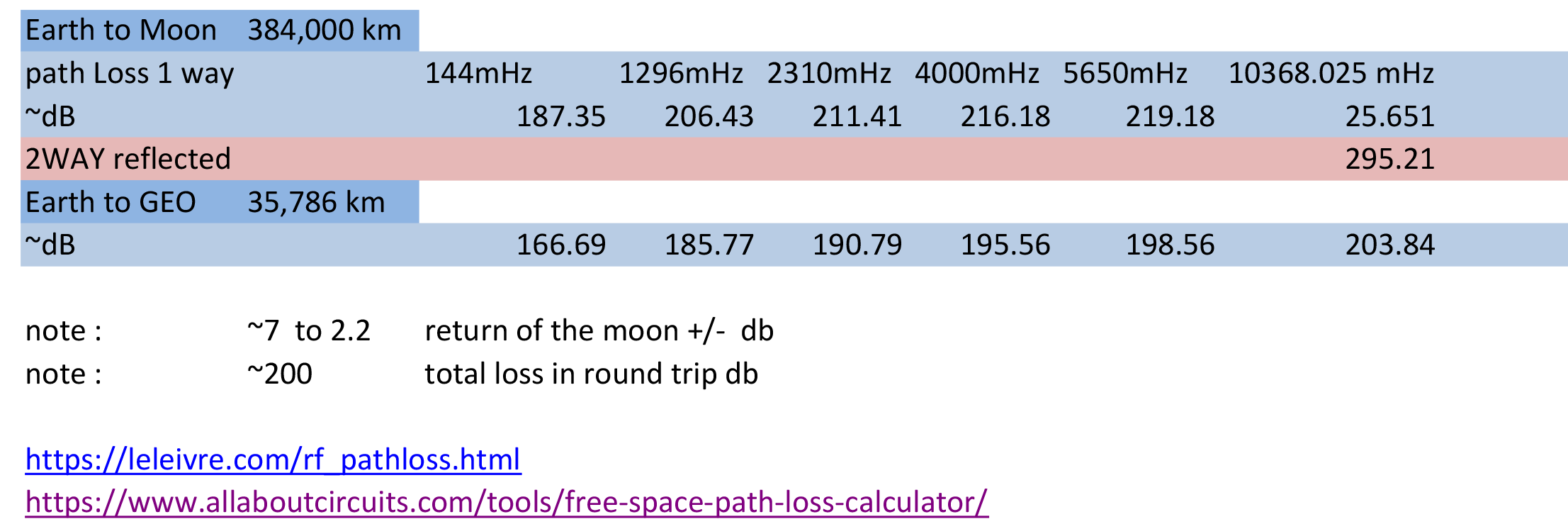
free-space-path-loss-calculator
Moon tables from the Navy
http://aa.usno.navy.mil/data/docs/AltAz.php
----------------------------------------------------------------------------------------------------------------------------------------
-Antenna tracking head-
Seen below at Field day 2011, with a 40cm and 2m yagi's tracking ARISS.
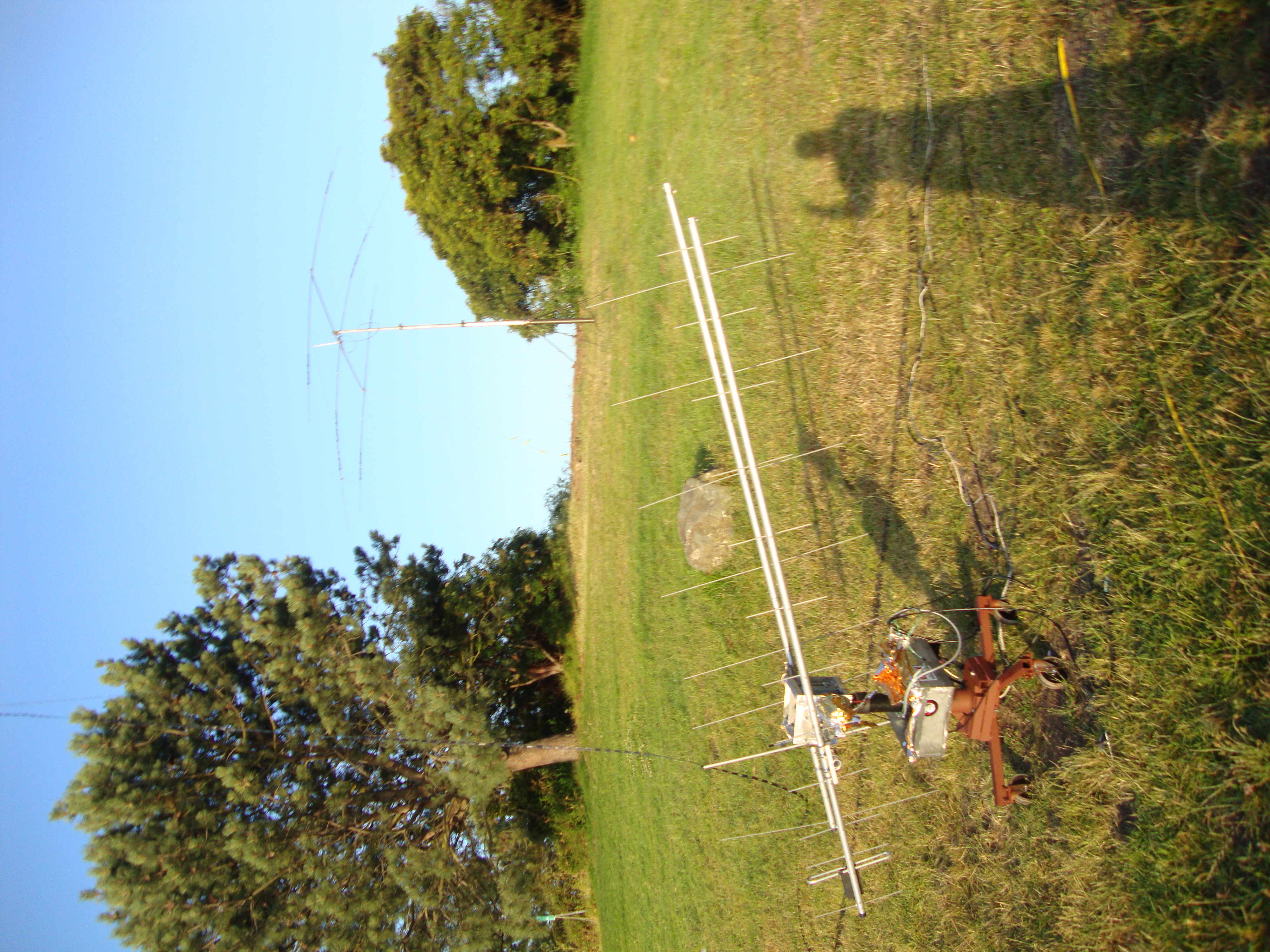
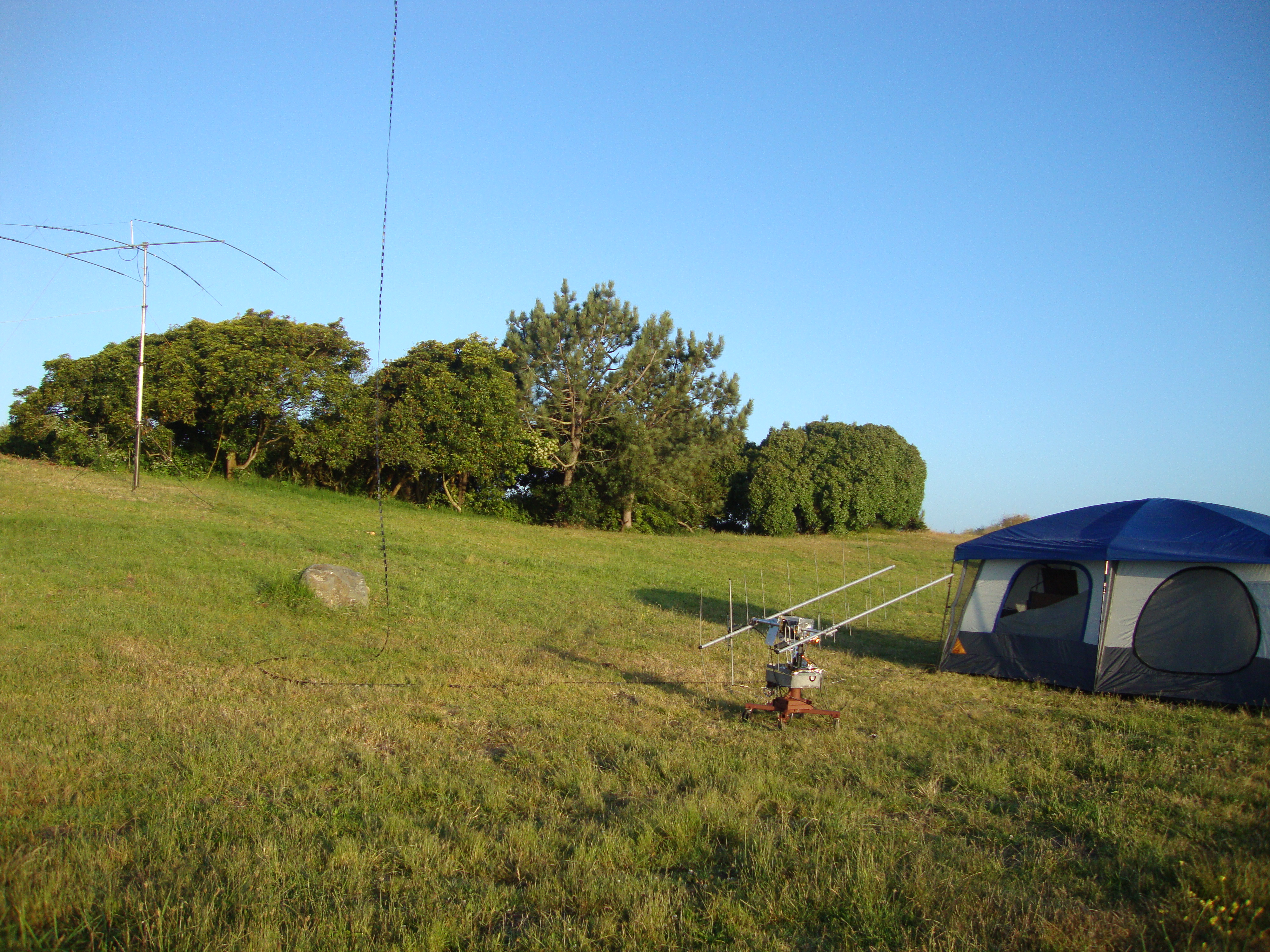
The super structure was stolen...RIP as scrap! I Planed to use the Make controller 2.0 to control the AZ and El, of 2 12Vdc motors run thou a PID loop with optical encoders and hall-Effects sensors counting the chain. A paper about picking the right antenna & "Satellite Tracking Heads"
Another good paper http://tdcom.fr/support/Sea-Tel/xx97/xx97_SWB_G.pdf
--MAKE Controller 2.0--
The web site hosting the device dropped off the Internet but before it did I cashed the site. Make controller 2.0

--Raspberry Pi--

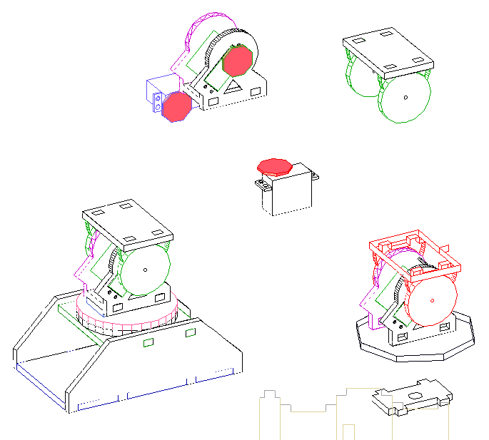
--Pan/Tilt Head design--
~~2022 Update~~
https://sgcderek.github.io/
~~~-END-~~~
-Home-