Milazzo, Carol F., WB2OZA, "Using The BC-645 on Amateur Television," A5, Vol 5:2, March-April 1975, pp. 3-5. Modifying a WWII surplus IFF transponder for amateur TV transmission.
The WWII surplus BC-645 or Navy ABA-1 IFF transponder is readily available from many surplus outlets or often found in local ham's junk boxes. It originally operated in the frequency range of 470-495 MHz, but is easily converted to cover the 70cm band of 420-450 MHz.
In order to accomodate the additional video circuits, all excess components are removed. It is necessary to remove all of the relays, potentiometers, the two centrally located rows of tubes and their associated circuitry from the under side of the chassis. The antenna connectors are replaced with SO-239's, the power connectors removed and the holes covered with aluminum sheet stock. The rigid coaxial line to the transmitter antenna jack may be replaced with a length of RG-58A/U. All that should remain is the receiver front end and the IF stages on the left side of the chassis and the transmitter circuits on the right side of the chassis.
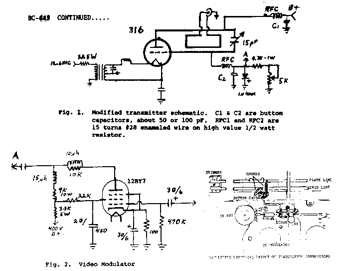
The conversion of the transmitter begins with soldering a 15pF mica capacitor trimmer (ARCO type 460) across the open end of the tuned line. The screw side of the trimmer should be soldered to the plate line as it will balance the lines better. Never forget to adjust this trimmer with a non-metallic tool! The trimmer allows a tuning range of 430-540 MHz. Next, remove the grid resistors, plate choke and wires and solder a new set of RF chokes to the lines about ¾" (19mm) closer to the open end. Pass the wires from the button capacitors as directly as possible through the inside wall of the tuned line compartment. The connections of these leads should be as short as possible. The leads connect to the new grid resistors, diode and plate capacitors.
The video modulator is built on the receiver side of the central divider to minimize the chance of RF feedback. The video peaking coils are wound on high value 1 watt resistors. The 10µH coil has 55 turns of #36 enamel wire and the l5µH coil has 65 turns. NOTE: The potentiometer cannot be wire wound but should be of a composition type element.
The best results are achieved when the following method is used to adjust the transmitter. Preset the grid bias pot to maximum and place a load on the transmitter output. Apply the filament power (12.6V AC @ 2 A) and the B+ voltage of 400V DC. The current should be near l00mA. There should be enough RF output at this point to light a 47 bulb very brightly. Tune the transmitter to the desired frequency with a non-metallic tool. The transmitter should be stable enough to remain within the passband of a Motorola T-44 receiver after about a 10 min. warm-up. Aim your camera at a dimly lit scene with the F stop closed to maximum. Now adjust the grid bias pot until the picture begins to smear, then back off a little. Open the F stop to normal and aim at a normally lit scene. Adjust the video input control to eliminate smearing. Any further adjustment should be limited to the video input level control only.
The transmitter runs approximately 30 watts input with 10 watts or so peak sync tip power output. Even though this transmitter is not capable of l00% modulation, it has been used to send stable snow free pictures over several miles. Simultaneous audio can be sent in a 4.5 Mhz sub-carrier or separately on another band. There is a good deal of F5 mixed with the A5 so wideband FM reception techniques could be tried.
If the receiver is to be used, the tuned lines of the 955 oscillator must be lengthened by ¼" (6mm). The 40 MHz IF output of the mixer can be fed to the IF stages of a TV set. An RF preamplifier can be added for improved sensitivity but the BC-645 receiver cannot approach the performance of modern receiving converters. The receiver could be used as a transmitter monitor or possibly be preserved for full duplex operation.
The widely available BC-645 offers economical means of putting a decent signal on the air. The GL-316 (VT-191) doorknob tube used in the transmitter is available from many surplus dealers for as little as $1 each.
