A Universal HF Magnetic Loop Antenna NEC Model
Design of a 4nec2 Model for Small High Frequency
Magnetic Loop Antennas
by Dr. Carol F. Milazzo, KP4MD (posted 16 September 2011)
E-mail: [email protected]
SUMMARY
This article describes an application of NEC modeling
to design and analyze the performance of high frequency
magnetic loop antennas with loop coupling.
INTRODUCTION
The small magnetic loop has received growing interest
as a relatively efficient compact high frequency antenna
for limited spaces. These antennas feature a
radiating conductor in a loop of either circular or
polygon shape of a circumference between 0.1λ and 0.25λ
resonated to the operating frequency with a
capacitor. These notes describe a NEC model
designed for analyzing and optimizing a loop-coupled
small magnetic loop antenna in an equilateral polygonal
configuration.
VERTICAL MAGNETIC LOOP ANTENNA
MODEL
The 4nec2 modeling program1 contains a model
of an 18-sided vertical magnetic loop with an 18-sided
coupling loop in the sample file named "models\HFshort\Magnetic.nec". This is a
free space model with fixed coordinates and perfect
conductors. When run with 4nec2, this model is
resonant at 7.05 MHz with an impedance of 1.15 ohms and
a radiation efficiency of 100%. With copper wire
conductivity specified, the model yields clearly
erroneous results, with negative calculated efficiency
and structure loss that exceeds the input power.
This model fails the average gain validation test2
with an AGT result of 4.86.
I decided to use 4nec2 variables and functions to design
a new model that would simulate an equilateral polygonal
magnetic loop antenna of variable dimensions and at
varying heights over a simulated ground. This
would facilitate the use of the optimizer function to
maximize impedance matching and efficiency in real world
situations.
The radius (distance from center to vertices) and
number of sides (from 3 to 18) of the loops are
specified and then the coordinates of the segment are
calculated using the sine and cosine values for each
angle increment about the center of each loop.
|

Figure 1. The 4nec2 sample "Magnetic.nec" model
fails validation with the Average Gain Test.
CONTENTS
|
Table 1. NEC Model Variable
Definitions
Variable definitions
|
Main Loop
|
Coupling Loop
|
Loop diameter
(input feet)
|
d
|
d2
|
Loop radius
(calculated feet)
|
r
|
r2
|
Loop wire braid
diameter (input)
|
dia
|
dia2
|
Loop wire braid
radius (calculated)
|
rad
|
rad2
|
| Loop wire outer diameter (input) |
od
|
od2
|
| Loop wire outer radius
(calculated) |
orad
|
orad2
|
Number of polygon
sides (input)
|
n
|
n2
|
Angle increment
(calculated as 360�/n)
|
inc
|
inc2
|
Segments per wire
|
seg
|
seg2
|
Height of loop
center above ground
|
ht
|
ht2
|
Height of main
loop base above ground
|
h
|
|
Distance between
tops of loops
|
|
h2
|
Operating
frequency = frq
|
frq
|
|
Resonating
capacitance = C
|
c
|
|
| Capacitor Q=2000 (typical) |
qc
|
|
| Capacitor resistance Rc
(calculated) |
rc
|
|
Figure 2 shows the model of a 6.5 foot diameter
vertical magnetic loop with an operating frequency of
7.05 MHz. The main loop is RG-8A/U coaxial cable
(outer diameter 0.405 inches) and the coupling loop is
RG-58/U (outer diameter 0.195 inches). Wires 1
through 18 comprise the main loop and wires 19 through
38 comprise the coupling loop. The resonating
capacitor is on wire 9 and the feed point is on wire
27. Optimizing for 50 ohm impedance and maximum
radiation efficiency (10.1%) yielded the loop dimensions
in feet listed in Table 2. Changing the main loop
from RG-8A/U cable (conductivity 4,500,000 mhos/m) to a
solid copper tube of the same diameter (conductivity
58,000,000 mhos/m) would increase the radiation
efficiency to 36.5%. This model passes the average
gain validation test with an AGT result of 1.0 (-0
dB). It was noted that the coupling loop diameter,
wire radius and loop separation distance all influenced
the calculated input impedance. For any specified
coupling loop wire radius, only one specific combination
of coupling loop diameter and separation from the main
loop yielded the non-reactive 50 ohm impedance
match. Download the Vertical
Magnetic Loop Antenna 4nec2 file.
Table 2. Magnetic Loop Antenna NEC
Model Calculations
*Values for
Horizontal Loop in Parentheses
Variable values
|
Main Loop
|
Coupling Loop
|
Loop diameter
(input feet)
|
d=6.5
|
d2=1.84 (1.61)*
|
Loop radius
(calculated feet)
|
r=3.25
|
r2=0.92 (0.80)*
|
Loop wire braid
diameter (input inches)
|
dia=0.32
|
dia2=0.135
|
Loop wire braid
radius (calculated feet)
|
rad=0.0133
|
rad2=0.00562
|
| Loop wire outer diameter (input
inches) |
od=0.405
|
od2=0.195
|
| Loop wire outer radius
(calculated feet) |
orad=0.0168
|
orad2=0.0081
|
Number of polygon
sides (input)
|
n=18
|
n2=18
|
Angle increment
(calculated as 360�/n)
|
inc=20
|
inc2=20
|
| Segments per wire |
seg=1
|
seg2=1
|
Height of loop
center above ground (feet)
|
ht=15.25 (12)*
|
ht2=17.40 (12)*
|
Height of main
loop base above ground (feet)
|
h=12
|
|
Distance between
tops of loops (feet)
|
|
h2=0.19 (0.14)*
|
Operating
frequency frq=7.05 MHz
|
frq
|
|
Resonating
capacitance pF
|
c=53.7 (53.6)*
|
|
Capacitor Q=2000 (typical)
|
qc
|
|
| Capacitor resistance Rc
(calculated) |
rc
|
|
When designing loops with fewer than 18 sides, the
corresponding unused numbered wires would be deleted
from this NEC model. During design, the voltage
source is first placed on the wire of the main loop
opposite from the capacitor side and the capacitor is
optimized for zero reactance to resonate the loop on the
operating frequency. The voltage source is then
moved to appropriate wire on the coupling loop.
HORIZONTAL MAGNETIC LOOP
ANTENNA MODEL
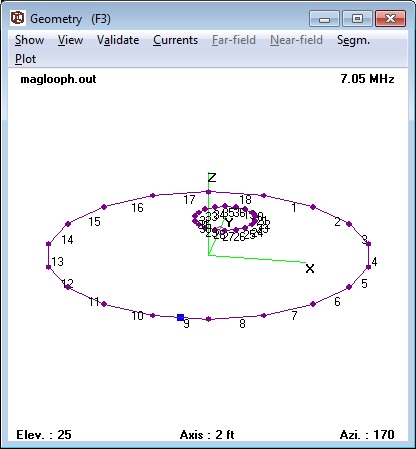
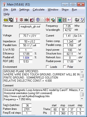
Figure 4 lists the NEC calculations for the loop in the
horizontal orientation. At 12 feet above the
ground, the coupling loop needed to be resized to 1.61
feet diameter and 0.14 feet separation to restore the
non-reactive 50 ohm impedance and the radiation
efficiency was a mere 1.7%. The radiation
efficiency increased to a maximum 9.5% by raising the
antenna to a height of 59 feet with the optimizer
function. Download the Horizontal
Magnetic Loop Antenna 4nec2 file.
CAUTIONS
The following NEC-2 modeling limitations should be
considered when interpreting these models:
- If the circumference of the coupling loop is less
than 0.07λ, the calculations may be questionable as
NEC-2 is unable to model such small loops.3
- The NEC-2 documentation specifically recommends that
closely space parallel wires be arranged so that the
segments are carefully matched. In models where
both the coupling and main loops are in close
proximity, the disparities in the segment lengths of
the loops may be significant. This situation
might be addressed by designing the coupling loop with
fewer and longer sides.4
- NEC-2 models of parallel wires of different
diameters (as has been well established) produce
highly erroneous values. As the model predicts
that main loop and coupling loop will be of different
wire diameters to achieve impedance transformation,
the significance of this guideline for parallel wires
where portions of the loops are nearly parallel is
uncertain.5
- Loops with fewer than 8 sides will require
increased segmentation of the wires in order to pass
validation with the Average Gain Test.
- Small changes to the number of sides of the coupling
loop have little effect on the results; however,
changes to the number of sides of the main loop will
require readjustment of the capacitor to restore
resonance prior to calculating performance due to
perimeter variation.
- Finally, I have validated models for the main loop
against a physical antenna8.
Validation with the feed through the modeled coupling
loop is pending.
ZERO PITCH HELIX MODELS
Owen Duffy, VK1OD, suggested using the NEC GH command
rather than the GW command to construct a loop as a
helix with zero pitch. In some NEC-2 programs as
4nec2, the GH command gives a divide by zero error when
the helix spacing and length are set to zero; however, I
found that the GH command will work in 4nec2 when these
parameters are set to a very small value such as 1e-100.
The following NEC files that use the GH command produce
models that yield identical performance calculations to
the previous models. Specification of the
variables n and n2 can produce loops of any number of
sides without requiring the addition or deletion of
lines to the NEC file; however, each side will be
comprised of only one segment. Such loops with
fewer than 8 sides fail validation with the Average Gain
Test.
- Vertical Magnetic Loop
Antenna 4nec2 file using GH command
- Horizontal Magnetic Loop
Antenna 4nec2 file using GH command
ALTERNATIVE COUPLING METHODS
At times, the 4nec2 optimizer function does not
converge on a best match of the 50 ohm transmission line
to the magnetic loop through a simple coupling loop.
Various alternative coupling methods such as the Faraday
loop, gamma match, and ferrite transformer all have
their proponents with accompanying controversy.
Doerenberg, N4SPP, has compared and documented his
experience with these various methods6 and
recommends the ferrite toroid transformer for its
simplicity while noting the need to vary the turn ratio
in order to maintain an adequate impedance match over a
4:1 frequency range. Toroid core coupling also permits
estimated measurement (through the transformation ratio)
of the loop impedance. Goff and Milazzo have described
the construction of magnetic loop antennas using toroid
matching transformers with variable turn ratios.7,8
REFERENCES
- 4nec2
antenna modeling software, Voors, A.
- "Modeling
the Unmodelable", Cebik, LB, W4RNL, Antennex,
July 2006
- "Recent
Advances to NEC: Applications and Validation",
Burke, G, March 1989
- "Dipoles:
Variety and Modeling Hazards", Cebik, LB, W4RNL,
Antennex, February 2007
- Amateur
Radio Archive, Radio Electronics, May 1998
- Magnetic
Loop Antenna for 80-40-30-20 mtr, Doerenberg, F,
N4SPP
- Portable
Magnetic Loop Antenna Version Two, Goff, R,
G4FON
- 14-30 MHz Magnetic Loop
Antenna, Milazzo, C, KP4MD
- Small
Transmitting Loop Antennas, Yates, S, AA5T
APPENDIX: 4nec2 Model Files
- 4nec2 Sample File
Magnetic.nec
- Universal Magnetic Loop
Model File (Vertical orientation) magloop.nec
- Universal
Magnetic Loop Model File (Horizontal orientation)
maglooph.nec
|

Figure 2. Vertical Magnetic Loop Model

Figure 3. Vertical Magnetic Loop Calculations

Figure 4. Horizontal Magnetic Loop Model

Figure 5. Horizontal Magnetic Loop Calculations
|


