Modeling Commercial Amateur Radio Antennas
Estimating Commercial Antenna Performance Through
NEC Modeling
Arrow OSJ 146/440 J-Pole, Cushcraft R7 HF Vertical, Diamond D130J (Icom AH7000) Discone,
High Sierra Sidekick, and Workman WHF40
by Dr. Carol F. Milazzo, KP4MD (posted 06 August 2011)E-mail: [email protected]
Arrow OSJ 146/440 J-Pole Antenna
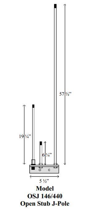
The Arrow OSJ 146/440 J-Pole Antenna is a vertically
polarized omnidirectional antenna. The manufacturer's
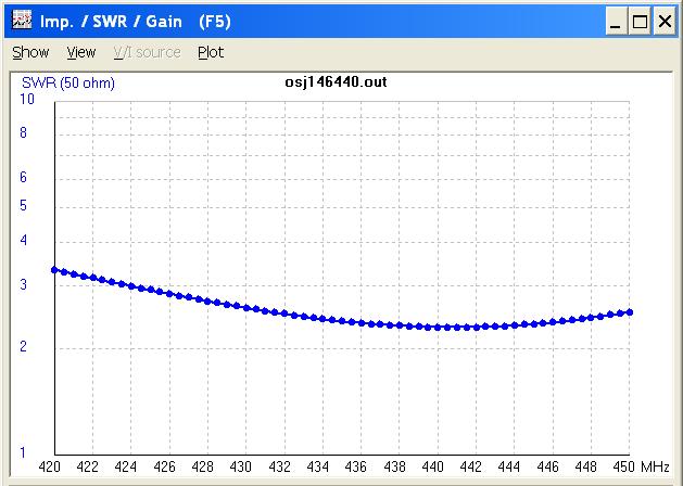
specifications1 state a VSWR of less than
1.5:1 over 143-149 MHz and 430-450 MHz and has been tested
to 1,000 watts.
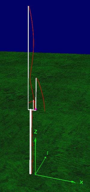
As this antenna is often mounted on metallic mast, it was
modeled both with and without the mast to demonstrate the
effect on the radiation pattern. When using the
dimensions provided in the manufacturer's literature,
4nec2's calculations of resonant frequency were several
MHz below the specification. Crothers2
also noted this discrepancy and postulated its cause as
the irregular shape and disparate effective diameter of
the horizontal shunt section. Therefore, the element
lengths in this NEC model were shortened for the 4nec2
model to render a frequency response comparable to the
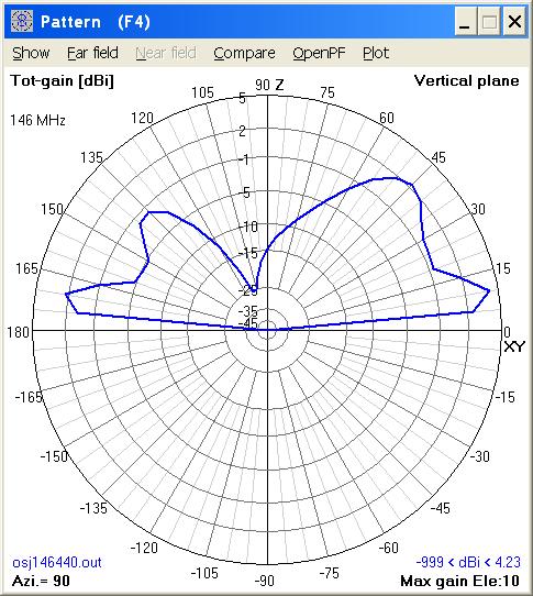
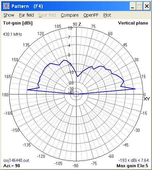
observed and published data. The following files and
elevation radiation patterns represent the 4nec2 antenna
model mounted at 80 inches (1 wavelength at 146 MHz) above
simulated good ground on a 1.2 inch diameter metal mast.
 |
 |
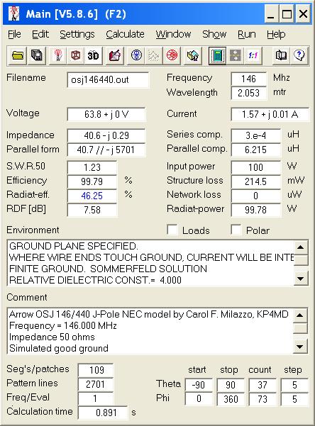
| Arrow OSJ 146/440 Performance on 146 MHz | Arrow OSJ 146/440 Performance on 430 MHz |
|---|---|
 |
 |
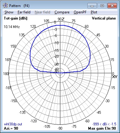
| Arrow OSJ 146/440 Pattern @ 80" on 146 MHz | Arrow OSJ 146/440 Elev. Pattern @ 80" on 430 MHz |
 |
 |
| Arrow OSJ 146/440 NEC Model SWR 140-150 MHz | Arrow OSJ 146/440 NEC Model SWR 430-450 MHz |
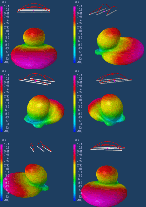
Arrow OSJ 146/440 4nec2 Model Files
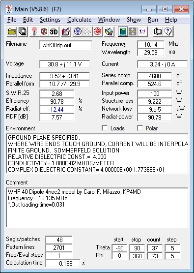
In free space
80 inches above ground
80 inches above ground on
metal mast
Arrow
OSJ 146/440 J-Pole Videos
References:
1 Arrow OSJ 146/440 J-Pole Antenna, http://www.arrowantennas.com/inst/OSJ146440.pdf2 "The J-Pole Antenna", Crothers C Bronson, AA1ZB
3 "The J-Pole Revisited", Richardson D, K6MHE, CQ, March 1998, 34-41
Arrow OSJ 146/440 NEC Model
Cushcraft R7 Vertical Antenna
The Cushcraft R7 is a multiband vertical antenna rated at
1800 watts peak power on the 7 through 28 MHz amateur
radio bands. Not owning one of these antennas, I
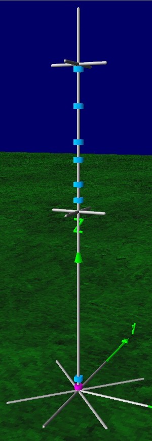
designed the 4nec2 model with the 4nec2
modeling program using the length and radius
dimensions in inches from the online
manual and the trap frequencies posted by Tait on
his web page Cushcraft
R5/R7 Maintenance and Repair. All segments
were between 5 to 6 inches in length. Although the
radial elements are stainless steel, for simplicity the
entire antenna was modeled as aluminum. A Q factor
of 250 was selected as representative of typical multiband
antenna traps. The inductance values were determined
using the 4nec2 optimizer function to obtain resonances in
the center of each frequency band, starting with 29 MHz
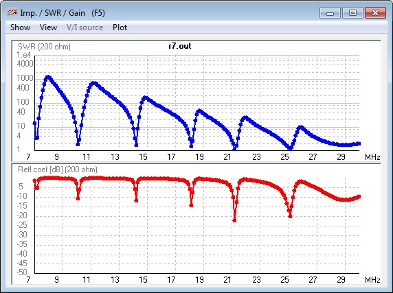
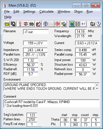
and progressing down towards 7.15 MHz. Standing wave
ratios were calculated for a characteristic impedance of
200 ohms due to the 4:1 transformer in the matching
assembly at the base. In the elevation radiation
patterns, 0° and 180° represent the horizon. The
azimuth radiation patterns are not shown as they are
circular. The patterns for a height of 5 feet over
ground were chosen as specified in the manual. The
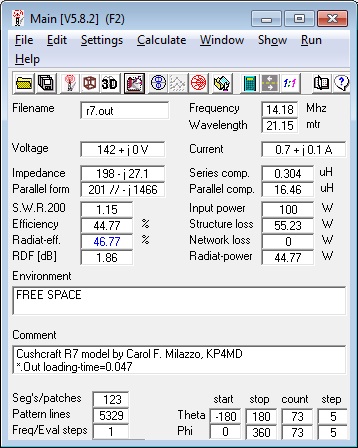
accompanying model files and radiation patterns represent
the antenna in free space and at a height of 5 feet above
ground as specified in the manual. For other
heights, one needs to change the height in feet (hft, the
first variable in the file).
SY hft=5 'Input height above ground in feet (default=5)
Cushcraft R7 NEC Model SWR vs. Frequency
Cushcraft R7 4nec2 Model
 |
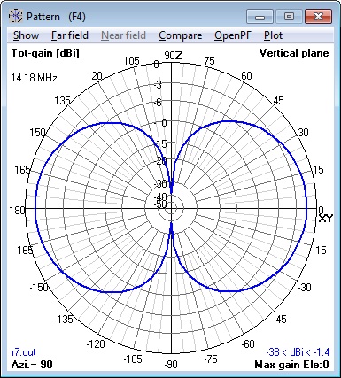 |
| Cushcraft R7 Free Space Performance on 14.175 MHz | Cushcraft R7 Free Space Pattern on 14.175 MHz |
|---|---|
 |
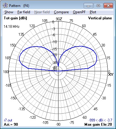 |
| Cushcraft R7 Performance @ 5 feet on 14.175 MHz | Cushcraft R7 Pattern @ 5 feet on 14.175 MHz |
Cushcraft R7 4nec2 Model Calculations
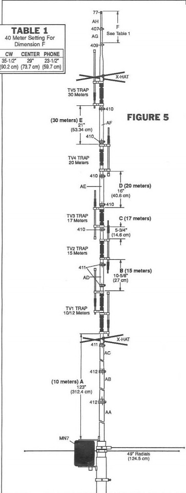
Cushcraft R7 Dimensions
Cushcraft R7 4nec2 Model Files
In free space at 5 feet above good ground
Cushcraft
R7
Videos
Feedback: Cushcraft R5 NEC
Model
On 3 March 2012, Peter van Latum PA0PVL from the
Netherlands wrote and sent his 4nec2 model and pictures
for the Cushcraft R5 vertical antenna (similar to the R7
but without the 7 and 10 MHz bands).
Cushcraft
R5
4nec2 Model File by PA0PVL Cushcraft
R5
4nec2 Screen Capture Files by PA0PVL
FHV Geerligs PA0FRI has also posted a detailed description
of the construction of the Cushcraft R5 vertical antenna
at http://pa0fri.home.xs4all.nl/Ant/R5/onhr5eng.htm.
On 14 April 2015, Nicolae Crisan YO5OUC from Romania
kindly sent his 4nec2 model of the Cushcraft R8 antenna (similar to the
R7 but with 50 MHz added). Cushcraft R8 4nec2 Model File
by YO5OUC
Please e-mail YO5OUC
if you have any idea for improvements regarding the
R8-Cushcraft antenna modeling/simulation
Diamond D130J (Icom AH7000)
Discone Antenna (A Universal Discone 4nec2 Model)
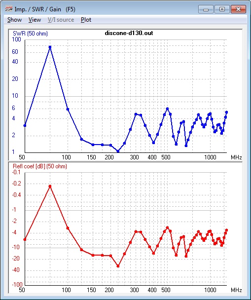
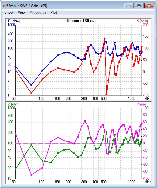
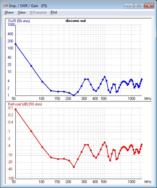
The Diamond D130J (also marketed as the Icom AH7000) is an ultra wide-band omnidirectional vertically polarized antenna designed to receive over the 25-1300 MHz frequency range. It can also be used for transmitting up to 100 watts (50 watts PEP on 6 meters) on the 50, 144, 222, 430, 900 and 1200 MHz amateur bands. The top vertical whip and loading coil may be removed if 25-50 MHz is not required. These 4nec2 models are for both configurations.
Rather than specifying fixed coordinates, this 4nec2 model was constructed using variables for the element dimensions and the GM NEC card to copy the elements around the vertical axis (a useful technique for antennas with radial symmetry). This facilitates the use of the 4nec2 optimizer function to customize the antenna design and to observe the effects of varying the antenna configuration and dimensions upon expected performance. The 4nec2 program automatically calculates the segmentation and the endpoint coordinates of all the antenna elements.
In his article "Notes on HF Discone Antennas"1 Cebik described NEC-2 code limitations that also affect VHF discone models. The specified default values of the variables yield models that pass all validation tests. However, for the 0.1" default element radius of this model, the 4nec2 program reports segment length validation errors for s values less than 0.6" or greater than 3" depending on frequency, segment angle errors for s values less than 1", and Average Gain Test (AGT) failures for disc to cone apex separations less than 1" or greater than approximately 6" depending on frequency. Therefore, the source wire length and the disc-to-cone separation of these models has been adjusted to yield the best AGT scores and therefore the most reliable model values as measured internally to the model.
 |
 |
| D130J
Discone Antenna SWR (50-1300 MHz) |
D130J Discone Antenna Impedance (50-1300 MHz) |
|---|---|
 |
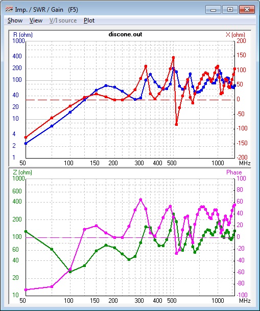 |
| Discone Antenna without Top SWR (50-1300 MHz) | Discone Antenna without Top Impedance (50-1300 MHz) |
Diamond D130J
(Icom AH7000) Discone 4nec2 Model Files
With Top Section (25-1300
MHz)
Without Top Section (100-1300
MHz)
Discone
Antenna Videos
References:
- "Notes on HF Discone Antennas", Cebik LB, W4RNL
- "A Homebrew 100-1300 MHz Discone Antenna for $15", Milazzo CF, KP4MD
- 4nec2 file for Homebrew 100-1300 MHz Discone Antenna
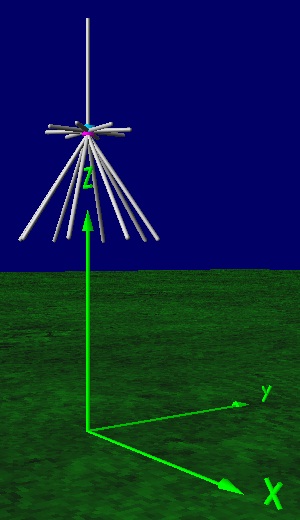
Diamond D130J Discone 4nec2 Model
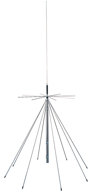
Diamond D130J Discone Antenna
| Variable
definitions |
Variable |
Default |
|---|---|---|
| Input feed point
height (in.) |
hgh |
120 |
| Input disc radial
length (in.) |
dsc |
11.5 |
| Input cone radial length (in.) | rdl |
34 |
| Input segment length (in.) | s | 1 |
| Input # segments in source wire |
sn |
2 |
| Input radial element radius (in.) | rad |
0.1 |
| Input number of spokes |
sp |
8 |
| Input cone angle
(90°=horiz) |
ang |
34 |
| Input design
frequency (MHz) |
f | 222 |
| Input top section
length (in.) |
v |
30 |
| Input top section radius (in.) |
rad2 |
0.05 |
| Input top section
inductance (H) |
L |
1.07e-6 |


