Sonobuoy �Fox Hunt� Transmitter

Arduino Microcontroller and Military Surplus Transmitter Use for Hidden Transmitter Hunts

by Dr. Carol F. Milazzo, KP4MD (posted on 24 Jan 2015)
E-mail: [email protected]

CONTENTS
  • Introduction
  • Sonobuoys
  • Transmitter Modification
  • Morse Code Keyer
  • Interface
  • Operation
  • References
  • Return to KP4MD home page
  • Sonobuoy transmitter
    1. Sonobuoy transmitter
    Sonobuoy Tuning Components
    2. Sonobuoy tuning components
    Sonobuoy schematic
                          diagram
    3. Sonobuoy schematic diagram

    INTRODUCTION

    This objective of this project is to use a military surplus transmitter for a hidden transmitter hunt1 conducted by the River City Amateur Radio Communications Society in Sacramento, CA.  In this competitive activity, also known as fox hunting, participants use radio direction finding techniques to find low power radio transmitters (usually within the 144 MHz amateur radio band) that are hidden within a defined search area.  This activity helps develop skills that are useful in search and rescue operations and interference mitigation.

    SONOBUOYS

    Sonobuoys3 are small low power VHF radio transmitters with attached hydrophones that are dropped into the ocean from aircraft or ships for submarine surveillance.  In the early 1970's, amateur radio operators commonly used modified vacuum tube-type crystal-controlled commercial mobile radios on the amateur VHF FM repeaters2 that were then becoming popular.  Due to their low cost, modified surplus sonobuoys became a popular alternative transmitter for FM repeater operation.  The sonobuoy transmitter board used here had been purchased in November 1971 for about $20 at the Leeds Radio surplus store on 57 Warren Street in New York City's Radio Row. Any other available low power FM transmitter or handheld transceiver would suffice for this project.

    TRANSMITTER MODIFICATION

    The original sonobuoy circuit consists of an 18 MHz crystal-controlled transistor oscillator and several multiplier stages driving a final amplifier stage that delivered about one watt output in the 160 MHz range.  Here is a simple procedure that WA2ZSD and K2BO described in 1971 replacing the crystal with a custom ordered 8 MHz unit, and to re-tuning the oscillator tank circuit and the multiplier and amplifier stages to transmit in the 144-148 MHz frequency range. 

    1. Remove 4 turns from Coil "C".
    2. Install a crystal socket or crystal of desired frequency.  Works with either 8 MHz or 24 MHz crystals.
    3. Ground circuit board section "X" to chassis.  This is not necessary for preliminary tune-up.  Add heat sink to transistor.
    4. Attach No. 47 Pilot lamp (or power meter with 50 ohm dummy load) to output terminals.
    5. Apply 12 volts DC to terminals shown.  Be careful of polarity.  Not over 13.5 volts recommended.
    6. Put 0-250 mA meter in DC power line.
    7. Tune Variable Capacitor "1" and Padder "2" for maximum current.
    8. Lamp will show faint glow.
    9. Tune Capacitors "3" through "9" for maximum brilliance of Lamp.  Tune in numerical order shown.
    10. Coils "A" and "B" are for frequency adjustment.  Turn B slug as far in as possible as a starter.  Tune Coil "A" only after Coil "B" has been tuned.  These coils permit a frequency change of about 5 kHz.
    11. When properly tuned, current should be approximately 180-200 mA.
    12. With antenna connected in place of dummy load, Capacitors 8 and 9 may require a slight adjustment.  Tune for maximum output using field strength meter or pick-up loop with RF rectifier and 0-1 mA meter.
    13. A one transistor modulator is all that is needed to obtain 5-7 kHz deviation using a carbon mike.  A clipping circuit in the modulator is desirable but not absolutely necessary.
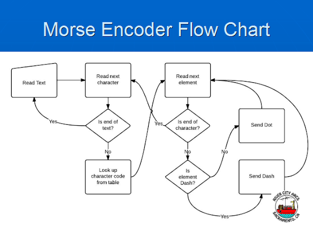
    Morse code encoder flow chart
    4. Morse code encoder flow chart
    Arduino microcontroller code
    5. Arduino microcontroller code
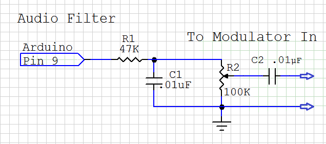
    Arduino audio interface
    6. Arduino audio interface

    7. Sonobuoy Fox Transmitter under test

    MORSE CODE KEYER

    The hidden transmitter needs a distinctive modulating signal to distinguish it from other transmitters in the frequency range and to comply with station identification requirements.  Atkinson has published a program4 for the low-cost Arduino microcontroller that converts keyboard input text into Morse code sounded on a piezo buzzer.  I completed Atkinson's code look-up table and Kevin Hooke5, KK6DCT coded an endless loop to repeatedly send an identifying message.  The Arduino program6 first defines pin 9 for the audio output and the on board pin 13 LED for visual indication, sets the tone frequency, the length of dots, dashes and spaces, then executes as follows:

    1. Start reading the text message.
    2. Fetch the next character.
    3. If this is the end of the message, proceed to step 1, otherwise proceed to step 4
    4. If the character is a space proceed to step 5, otherwise proceed to step 7
    5. Wait for the duration of a word space
    6. Proceed to step 2
    7. Look up the character in the table and fetch the corresponding Morse code.
    8. Read the next element of the Morse code.
    9. If this is the end of the Morse code character, proceed to step 10, otherwise proceed to step 12.
    10. Wait for the duration of a character space
    11. Proceed to step 2.
    12. If the Morse code element is a dash, proceed to step 13, otherwise proceed to step 18.
    13. Turn on the audio tone LED and the on board LED
    14. Wait for the duration of a dash
    15. Turn off the audio tone and the on board LED
    16. Wait for the duration of dot
    17. Proceed to step 8.
    18. Turn on the audio tone LED and the on board LED
    19. Wait for the duration of a dot
    20. Turn off the audio tone and the on board LED
    21. Wait for the duration of dot
    22. Proceed to step 8.

    Another similar Arduino sketch7 by Mark Rodgers, KC8GRQ, was discovered after this project was completed.

    INTERFACE

    The fixed amplitude square wave at pin 9 of the Arduino microcontroller can be adjusted to provide the desired modulation level.  Figure 6 is the schematic diagram of an audio interface circuit by Fowler8 that I have modified for this purpose.  R1 and C1 constitute an optional low pass filter, R2 adjusts the modulation level, and C2 decouples the DC component of the Arduino output from the varactor modulator in the transmitter.

    OPERATION

    A preliminary on the air test was conducted with an attached eight inch flexible antenna.  When powered by a 7.2 volt 2300 mAh NiMH battery the Arduino alone draws 30 mA current.  A frequency deviation of 3 to 3.5 kHz was measured with an RTL-SDR receiver.  The Morse code signal was clearly heard with a Yaesu FT-60R handheld radio at a distance of up to 2000 meters when transmitting 50 mW with a J-pole antenna at 6 meters height, and up to 500 meters when transmitting with a Larsen KD4-270 flexible antenna attached to the transmitter.

    REFERENCES

    1. Transmitter Hunting, https://en.wikipedia.org/wiki/Transmitter_hunting
    2. Amateur Radio Repeaters, https://en.wikipedia.org/wiki/Amateur_radio_repeater
    3. Sonobuoy, https://en.wikipedia.org/wiki/Sonobuoy
    4. Morse Code - Encoder, Atkinson, MH, http://multiwingspan.co.uk/arduino.php?page=buzzer2
    5. Hooke, K, KK6DCT, http://www.kevinhooke.com
    6. Arduino Morse Code sketch
    7. Fox Hunt Beacon, Rodgers, M, KC8GRQ, http://www.mark-rodgers.com/fox-hunt-beacon/
    8. Arduino Audio DAC Options, Fowler, D, http://www.uchobby.com/index.php/2008/01/08/arduino-audio-dac-options/
    Return to KP4MD Home Page
    Top