ICOM 746 and 746Pro
LCD Back Light
and Dead Transmitter Repair
Dave Sparks, KV5A

The
ICOM 746Pro has two well known problems. The LCD display back light
driver transistor will eventually dissipate way too much heat and fail.
In the worst case, the result is a carbonized PC board and
lifted
mounting pads. Your display goes dark. You can live without it but the
display is almost impossible to see in a low light environment. The
other issue is the sudden death of your transmitter. That
means
your backup transceiver will have to take up the slack while your 746
rig is off the the repair facility. Doing the repair yourself will save
you a bunch of time and money but do this only if you can work with
small SMD components and have the proper tools to do so. There are
several solutions published on line by hams who have had these
failures. You can decide if their solutions meet your
requirements. Mark, K5LXP, has a very informative article at the link
below.
Mark provides details for this repair I will not duplicate
here.
http://www.qsl.net/k5lxp/projects/746Pro/746ProNoTX.html
Ed, WA3WJS provides this intuitive article at
this link
below.
https://wa3wsj.homestead.com/IC-746Pro_Sudeden__Death_Fixes.pdf
The
following is my analysis and the repair I decided to do. I do not
guarantee your results if you attempt to duplicate my repairs but I
think you will find it is a thoughtful approach.
The 746/Pro
Sudden Transmitter Death
My
research of all the posts I read indicates there may be several
possible causes of the failure of RF transmit driver IC-151, uPC1678G.
Among them are ESD, excessive heat dissipation, and a high voltage
spike on the 5 volt supply line. All of these possibilities
are
plausible. The failures seem to occur over various periods of time and
under different circumstances making it difficult to pin down the exact
cause. Ed, WA3WSJ, posted an article on this issue. I was
convinced he was on to something. In short, he had a friend whose
coworker had a problem with a similar circuit design. He kept blowing a
like RF IC chip trying to get it to work, but why? The reason
discovered was that the manufacturer's design called for a nanoHenry
choke in the 5V supply line and not a uHenry choke. Thus, every time
the power supply was turned on the chip's collector output was hit with
a large inductive spike eventually blowing it out. Replacing the choke
with a smaller choke did the trick and the circuit worked just fine. If
heat dissipation is not the issue then adding a heat sink is not
necessary. So, with that in mind, instead of
duplicating
other repairs, I approached the repair as follows.
⦁
1. Replace IC-151 with a new uPC1678G available
from Circuitstransistors.com. $4.00 each plus shipping as of
May 1, 2018.
⦁
2. Replace C156 .0047 uf chip cap with a 20uf chip cap. (or two 10 uf
caps, DigiKey part number 445-11219-1-ND) This will filter
the
Vcc chip supply and eliminate any excessive inductive spike to the chip
output collector. This is likely the only modification really necessary.
⦁
3. Lift R157 10 ohm resistor from the +5.0 volt supply, stand it on end
attached to the pad nearest IC pin 8. Connect the anode end of a 2.7
volt zener (DigiKey part number 1N5223BCT-ND) to the lifted end of R157
and solder the cathode end to the transmit 8 volt line at R156 330 ohm
resistor. This will supply power to the chip only on transmit. This
might not be necessary but it does no harm.
⦁
4. Add a 1 mH choke (DigiKey part number RLB0608-102K-ND) to
the
center pin of the HRX connector (J1) and the PCB ground plane. This is
for added ESD protection. K5LXP suggests this and it too
does no
harm. Time will tell if my solution will hold up. So far so good.
Figure 1.
This is the ICOM 746Pro RF Unit PC Board where the driver chip circuit
is found. IC-151 is located on the left side.
Figure 2.
Close
up of the new uPC1678G chip installed and two 10 uF caps stacked to
replace C-156. Also shown is a 2.7 volt zener attached to the 8 volt
transmit supply line.
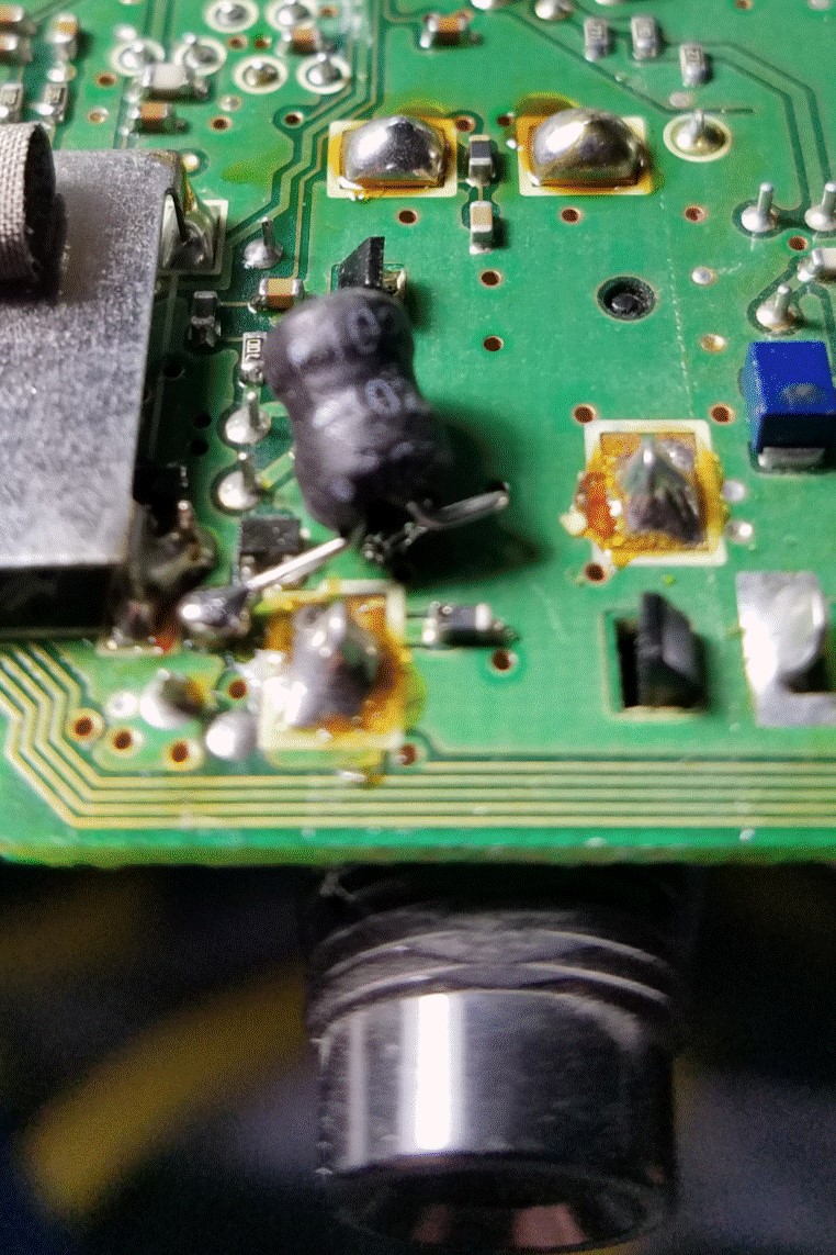
Figure 3.
A
1 mH choke is installed on the bottom of the board for added ESD
protection. The pin diodes were factory installed and were not changed.
Figure 4.
While
I had the radio opened up, I added the optional the CR-338 High
Stability Crystal Unit to the same board. This provides better
frequency stability and accuracy especially noticeable on 6 and 2
meters.
746
LCD Back Light
The
LCD back light issue eventually plagues every 746Pro. I bought my rig
at
a tailgate a few years ago and it was not long till the intermittent
back light on again and off again symptom appeared. Eventually it
stopped working all together and I lived with it for a long time. Now
is the time to get my back light back. The common cause of this failure
is excessive heat dissipation in the high voltage driver transistor,
especially when the brightness is set to less than 100%. The transistor
dissipates more power at lower brightness settings contributing to the
failure. The root cause is of course a very poor ICOM design.
KA1MDA has a very informative and detailed article here:
http://www.ka1mda.org/ham/homebrew/746/index.htm
Several
of the repairs I found on the WEB included adding a heat sink inside
the shield cage and that is ok, but the heat sink was not attached to
the tab of Q302 in any of these repairs. It was maybe touching the
plastic case because of the mechanical implementation. This was not
very effective in my opinion. The transistor tab is where the heat sink
needs to be attached to effectively cool the transistor
junction.
So, I decided to take a different approach.
I ordered more than one
of each part replaced just in case, well just in case... and then
thought about what I needed to do. Parts are available from DigiKey.
Direct replacements are Q302, 2SB1201-TL-E, C-303, EEE-1CA470SP, Cap
Alum 10uf, 20% 16V SMD, and C302, EEE-1CA100SR, Cap Alum 10uf 20% 16V
SMD. All the other parts came from my junk box. The copper
plate
is .0675" thick cut to fit inside the shield less about 1/16"all around
so as to not touch the PCB or the shield. The fiber shoulder washer
fits into a 1/4" hole in the shield. The mounting screw is 4-40 cut to
length to fit the thickness of the shield, cooper plate and the little
IC heat sink plus a few threads for the nut. The silicone insulator is
a strip cut to size from a silicone rubber oven glove available from
many grocery or kitchen supply stores. The material used is .052 "
thick. You might even have one at home already. The thermal
compound
and all the tools or other material to fabricate my heat sink assembly
were on hand.
Figure 5.
This
is the back of the front panel as removed from the body of the 746Pro.
The ribbon cables and connectors must be disconnected and the the
mounting screws are removed in order to carefully separate this board
from the remaining front panel circuitry. There are two pot mounting
nuts that also must be removed.
Here is a video detailing the disassembly of the front
panel.
https://www.youtube.com/watch?v=3JWFYIl3zTc
Figure 6.
The
defective Q302, 2SB1201, is shown here in the bottom right of the
shield. The PC board shows discoloration due to excessive heat.
Figure 7.
The
transistor and associated capacitors were removed. The pads where
Q302 was
soldered lifted from the PCB. The PCB is burned and the surrounding
area is discolored. I scraped as much of
the carbon off the board as possible. The shield around the components
was removed to effect the repair.
Figure 8.
Since
there is no way to secure the transistor to the PCB as in the original
design, I chose to mount the transistor vertically and attach a heat
sink directly to the transistor tab. The copper sheet shown here is
slightly more thick
than a penny. Notice the cut out for clearance of
C-302, 10uf cap. Both (C-303) 47uf, and (C-302) 10uf,
capacitors are
replaced in case they were damaged.
![]()
Figure 9.
The
heat sink must be insulated from the shield since the collector is at a
high voltage potential. I used a small strip of material from
a green colored silicon oven glove. It is a good heat and electrical
insulator. I
added a small IC heat sink for added radiation of the heat. The
assembly is mounded to the inside of the cage with a 4-40 screw and a
fiber shoulder washer on the outside of the cage. Thermal grease is
applied between the copper and the black heat sink.
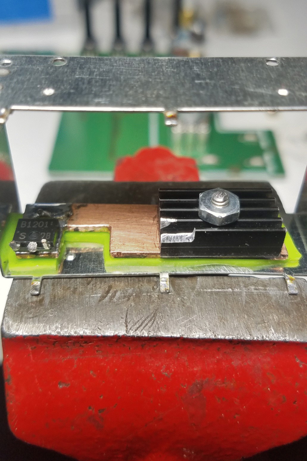
Figure 10.
Q302
is solidly soldered to the copper sheet. A small amount of the black
heat sink is filed away to clear a nearby transistor. The legs of
transistor Q302 are bent up to enable adding #30 wire wrap wire to make
the connections to the PCB.
Figure 11.
The
heat sink assembly is mounted to the shield, and Q302 connections are
soldered to the proper points on the PCB with #30 wire wrap
wire.
Red nail polish is painted on the board to cover an area of exposed
ground plane and to provide mechanical stability for a loose trace on
the PCB. A small piece of the silicone material is between the PCB and
Q302 legs to insulate it from the near by ground plane.
Figure 12.
I
drilled several holes in the shield lid just above the black heat sink
to facilitate the escape of radiated heat. An additional piece of the
silicone insulator was glued inside the lid just above Q302 as mounted
to prevent the copper sheet from possible contact with the lid. The
mounting screw is tightened enough to prevent rotation of the heat sink
assembly within the shield. I applied locktite to the 4-40
screw
threads during assembly. With the silicone in place at the top and
bottom of Q302 the heat sink will stay in place.
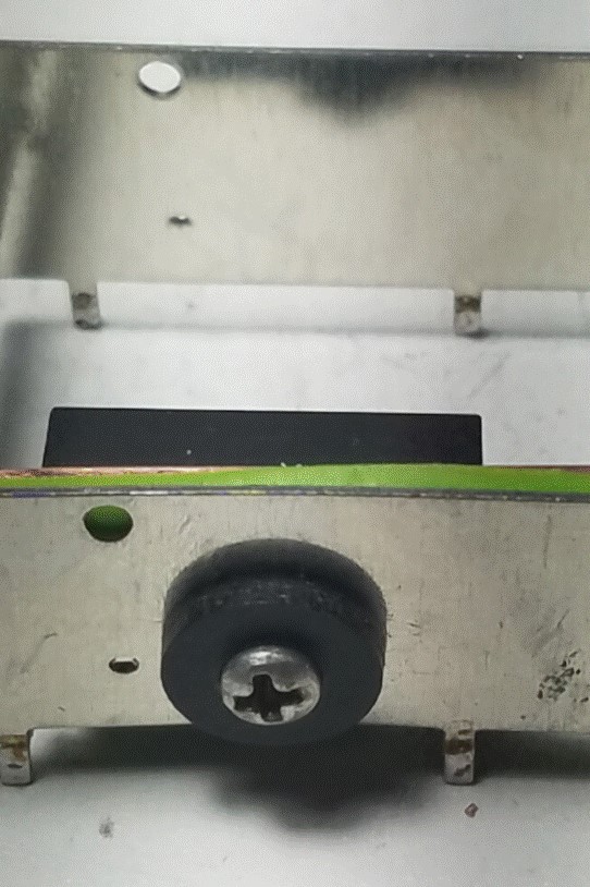
Figure 13.
The
PCB is now re-attached to the front panel assembly. The mounting screw
head on the shield is very close to the encoder body though it is not
touching. For added protection, I put a piece of electrical tape on the
encoder body just in case anything moves. If you look carefully you can
see the black shoulder washer on the outside of the shield.
The head of
the screw could be filed down
for greater clearance but I did not think it was necessary,
but that
depends on the particular hardware used in any case.
Figure 15.
After
a careful re-assembly of the front panel and installing the top and
bottom
cover back on the radio, I'm ready for the the smoke test. Holy Cow!
The display is fixed and the transmitter is back to full output power.
The transmitter is working like new too. Happy days are here
again!
Parts are available from DigiKey for the Back Light
repair. Direct replacements are Q302, 2SB1201-TL-E, C-303,
EEE-1CA470SP, Cap Alum 10uf, 20% 16V SMD, and C302, EEE-1CA100SR, Cap
Alum 10uf 20% 16V SMD. All the other parts came from my
junk box.
The copper plate is .0675" thick cut to fit inside the shield less
about 1/16"or more all around so as to not touch the PCB or the shield.
The fiber shoulder washer fits into a 1/4" hole in the shield. The
mounting screw is size 4-40 cut to length to fit the total thickness of
the shield, cooper plate, silicone insulator, and the little IC heat
sink plus a few threads for the nut. The silicone insulator is a strip
cut to size from a silicone rubber oven glove available from a grocery
or kitchen supply store. The material I used is .062" thick. The
thermal compound, other supplies and all the tools to perform this
repair were on hand. Thanks to K5LXP, WA3WSJ, KA1MDA and many
others for their contribution to the understanding of these problems
and their take on subsequent repairs.
Now on to the next project.
If you have comments or questions please email.
73, KV5A, Dave
[email protected]
