N0NJY
Amateur Radio
S-Pixie
40m QRP kit
(10
November 2018)
A
couple of months back I purchased a "Super Pixie" 40 meter (7.023
Mhz) kit via Amazon.com for about $8.00 US. Since I am
temporarily back in Colorado, I collected the kit, along with my
tools a few other things to bring with me so I can build the
device.
I
also have a second slight more expensive rig on order that will
cover most of 20 meters, has a 5 watt output, and a small digital
display to build. I'll write more about that at a later
time.
An
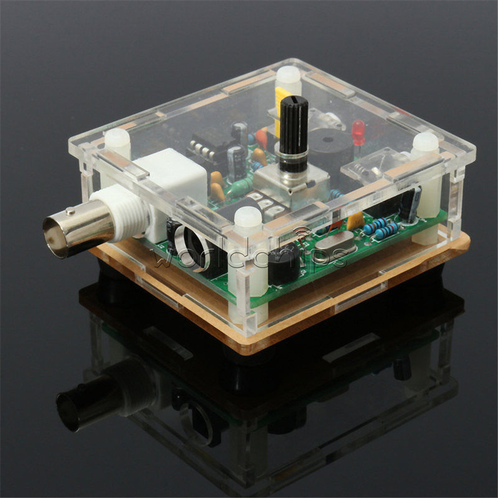
assembled S-Pixie Kit
At some point in the next few days, I'll
snap a few images to load here of the assembly process and upload them
to this article. I'll also write a review on it (assuming I can
get a decent antenna put together to use with the little rig).
Here's a picture of the unassembled
device, all the parts laid out so that they can all be seen. I
did not take these two photographs, but this is what mine looks like:
More
to follow in a few days!
11
November 2018 - Veteran's Day (Thanks to those who served!!)
I
started the construction of the Super Pixie QRP transceiver a couple
of days ago and took a few pictures as I was going along. It's
been, unfortunately, about three years since I picked up the soldering
iron for anything more extensive than putting a connector
together. My soldering leaves something to be desired. I
had to pick up a new soldering iron (a Weller, 25watter got it at
Lowes Hardware) because my ancient (about 40 years old now) Weller is
60 watts and comes with various tips, none of which I own any more, to
set the temperature values. Apparently it used some inductive
heating or something for the tip, and mine was a 700 degree F tip,
which is pretty dead now, rotted away from almost a half century of
soldering hi hi.
The
new one was unfamiliar, and of course, I'm out of practice. I
suspect when I'm done, I'll be doing some trouble shooting.
/sigh
Here's the
pictures I took. I host them at a site called imgur.com to prevent over
load of bandwidth on qsl.net.
Unpacking the
Pixie
Unpacking -
Part 2
Circuit Board
Back Side of
Circuit Board
Parts Laid out
on Table
Partially
assembled
I started
putting it together, and discovered a few things. First,
understand I'm in a less-than-optimum environment. I don't have my
old work desks, and lab I had in my old house any more. Second, I
don't have ALL my tools, and had to fake a few things. Finally,
the lighting in the bedroom where we stay is poor. My cataract
surgery from 2016 is more or less "holding" and my eye sight is great in
my right eye, my shootin-eye is awesome, but I need reading glasses to
see up close, and work.
I discovered
that the combination of not-so-great lighting, plus needing stronger
glasses was giving me fits trying to solder, and some of my connections
are NOT my old, NASA spec style like they used to be. I also
found out, I get tired of working on close up work, a LOT quicker
quicker than I used to get. Unfortunately, I still have the "I
gotta get this job done ASAP" mentality that came with me from my
military and government contracting days. I still have not learned
to slow down and live on "Island Time" when it comes to this stuff.
That means I
rushed through putting that board together, and what should take an hour
for me in my prime, took two and a half, and I did a crappy job.
So, I packed it all up and put it into a baggie for now. I'll get
back to it when I relax for a day or so, and visually check everything
under the magnifying glass, under bright light, and ensure my solder
connections are good, and I managed to get all the parts in correctly.
While doing the
assembly, some problems came up.
- 1. There are no instructions.
- 2. Had to download instructions.
- 3. Instructions are partially in
Chinese.
- 4. Parts list was readable, so I
knew R1 from R7, and D1 from Q2, etc
- 5. The bridge rectifier is NOT well
marked, and might NOT be installed right. (I'll check when I
inspect)
- 6. NO information on the circuit
board vs electrolytic caps. Image showed the Minus (-) side going to
the "white spot" on the component location.
- 7. I probably got the
electrolytics in board correctly.
- 8. Colors on the resistors
aren't as - clear as they used to be... I had to ohm each of them
out to be sure!
- 9. My eyes ain't what they
used to be.... (Neither is my voice or other things.....but I
digress)
At this point, I am going to stop and
I'll get back to this tomorrow, inspect the board, and check for
problems, build a small battery supply, and figure out some kind of
temporary antenna and dummy load. (Note, there IS a large 2-3 watt
50Ω resistor, which I can only assume is supposed to be used as a dummy
load.)
Home
Table
of Contents
Please
email me at [email protected] about broken links,
thanks!
All Site material © N0NJY,
Rick
Donaldson,
1997-2018


