The interface I built has a few unusual wrinkles that I thought are worth writing up. These include using a transformer that is far from 1:1 to improve a self-powered VOX scheme, and adapting one circuit to two radio types.
My homebrew PC-radio interface uses ideas from several published designs, chosen to meet the following goals:
One can send audio both ways between a computer and a radio transceiver, for digital modes such as PSK31, with not much more than direct cables, plus perhaps a few resistors to reduce signal strength where needed, e.g., between the PC line output (100mV) and the radio mic input (1-10 mV).
But, most interfaces add isolation between the computer and the radio, passing the desired audio signals but blocking hum and RFI. This is typically done using transformers (for audio) and optocouplers (for PTT switching). The isolation avoids connecting the "ground" of the different devices to each other.
Most PC-radio interfaces use a digital line from the PC, typically part of a serial port (whether actual or emulated via USB), to key the radio's PTT. To keep things simple, an alternative is to key the radio when a signal appears in the audio output from the PC. With such a VOX circuit the exact timing of the PTT is not as precisely defined, but that is usually not an issue.
Some minor annoyances with VOX include the need for a minimum level of audio signal to ensure clean keying, and the need to configure the PC software so as not to output audio while receiving.
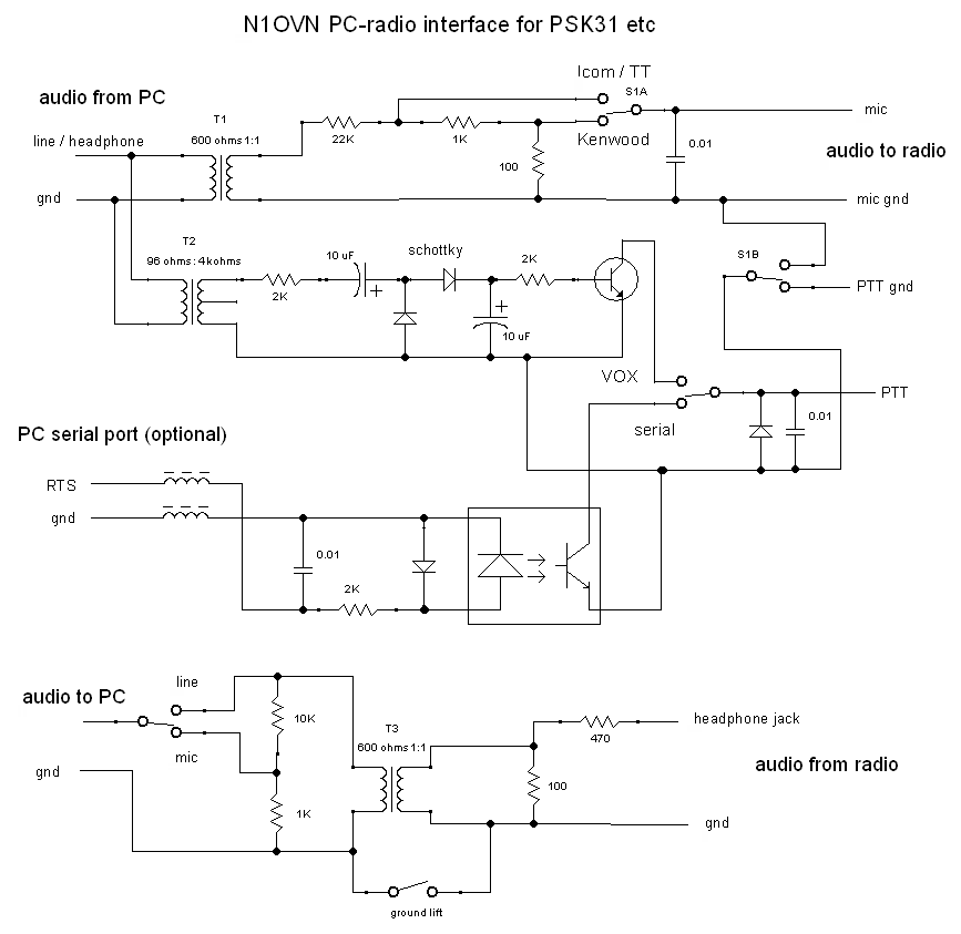
My plan was to use a step-up transformer for the VOX circuit, and another similar transformer in reverse, i.e., step-down, for the mic audio. That way the mic and PTT "grounds" can be isolated from each other as well as the PC side. And the plan also included an optocoupler for a serial-port PTT option.
In principle, a single transformer can be used for both the mic audio and the VOX, if the optocoupler can then be used to isolate the PTT from the mic grounds. Alas that means that the ground on the input side of the optocoupler is connected to the mic ground - that connection needs to be broken when in serial-port PTT mode, to isolate it from the serial port ground. That complicates the mode switching.
Another issue is whether the VOX circuit would produce a high enough DC voltage to activate the infrared LED within the optocoupler. It needs about 1V as compared with about 0.65V for a transistor B-E junction. With the large step-up in the transformer, plus the voltage-doubler rectifying circuit, this may be feasible.
Nevertheless, I ended up using separate transformers for the mic and VOX functions, since the circuit is simpler overall, and the extra transformer is cheap. I used a more common 1:1 transformer for the mic audio, and stepped the signal down with resistors.
S1, a DPDT, changes both the PTT grounding arrangement and the mic signal level between the Kenwood and TT/Icom modes.
The PC audio input and output grounds are also kept separate. A "ground lift" switch allows bridging the PC and radio grounds, which in some cases actually reduces noise. A mic/line switch allows fitting the signal level to fit the type of audio input available on the PC.
I skipped having audio level control pots in the interface, since both the radio and the PC already have such adjustments on both their inputs and their outputs, so why replicate that functionality.
With no serial port and no power source, I needed to generate enough voltage from the presence of the audio signal from the PC to drive the PTT transistor. This is achieved by a combination of a step-up transformer and a voltage-doubling rectifier circuit. The diodes should conduct at a voltage lower than the 0.7V typical of silicon diodes. Germanium diodes (0.2V threshold) would be ideal, but I used silicon Schottky type diodes (1N5819, 0.3V threshold). (The other diodes in this circuit are generic small-signal silicon, as is the PTT switching transistor.)
I also included a standard opto-isolator type PTT circuit that can be driven via a serial port, although I may never use that feature, since the VOX circuit works well, after some tweaking of the R's and C's.
If I were to build it again, I would change the following details:
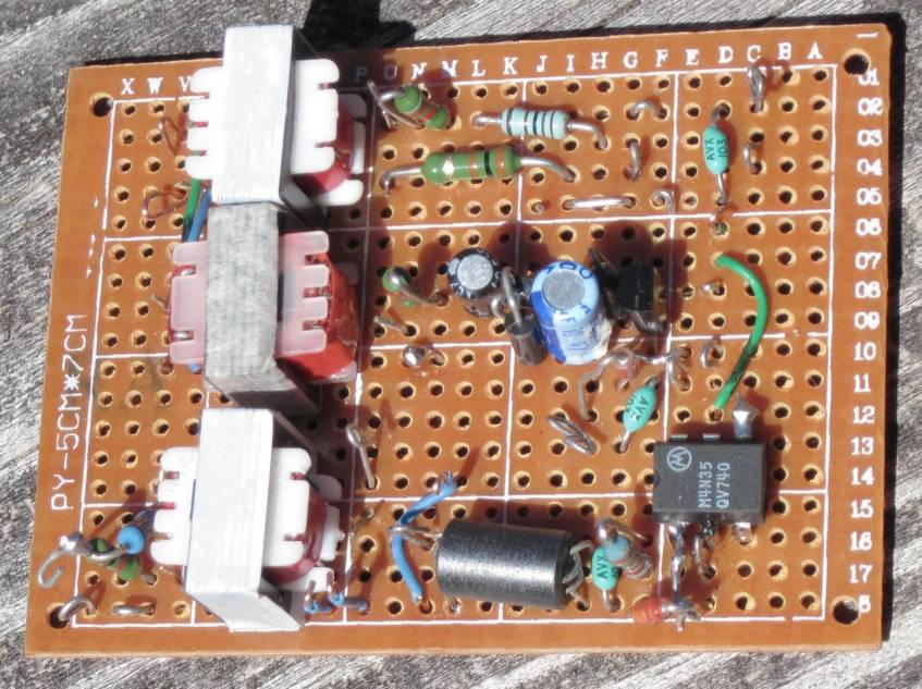
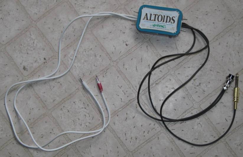
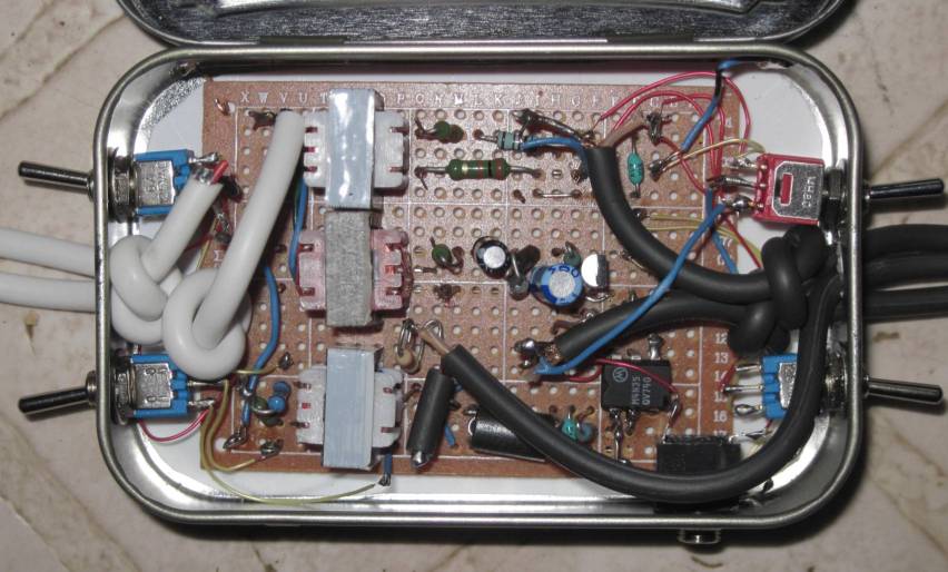
I built it on a perf board mounted in an Altoids tin. All the inputs and outputs could have been done via jacks, but that would just increase the probability of a loose, wrong, or pulled-out connection somewhere, so I hardwired the cables to the circuit as seen in the photos. (I did later add a 3.5mm stereo jack as an afterthought, as an easy way to connect to the mic jack on the Argosy.)

There is a sheet of plastic inserted between the board's back side and the tin. The whole circuit is isolated from the altoid tin itself, except for one grounding point at the radio mic ground. A couple of filter capacitors are used to try and reduce any pickup of stray RF while transmitting. And of course the connection cables are shielded.
I found the needed transformers online, but the un-common 96-ohm to 4 kiloohms type (or similar) could be replaced with the far more common 1Kohm to 8 ohms type. The 8 ohms side would connect to the PC audio output, with a resistor in series of about 20 ohms to avoid loading the PC audio output with a lower impedance than it can drive without distortion. The optoisolator was pulled from an old PC modem card, as was the binocular ferrite bead used in the serial port input.