I have embarked on a project to design and build an add-on to simple CW transmitters to enable them to transmit PSK31. A computer would still be needed, but no an SSB rig. For ultimate portability, perhaps a smartphone could be used as the "computer. An Android PSK31 app already exists!
The idea is to demodulate the audio from the computer, to determine phase flip times and the envelope shape, and use those signals to generate a "DC" (16 Hz) modulating signal. The connection to the transmitter would be by inserting a passive double-balanced diode-based mixer (SBL-1, etc) between some low-power stages in the transmitter. BPSK (31 and perhaps 64) only, of course, not QPSK or any other digi-modes.
My aim is to design a gizmo that is adaptable to most common QRP CW rigs, and that many hams who are not comfortable building their own RF circuits would find easy to build and use on the rig of their choice (especially if somebody eventually sells it as a kit), and affordable too (in the context of being an add-on to an inexpensive rig).
My draft design only uses 2 cheap and simple chips, and only handles audio (and lower) frequencies except for the input and output of the balanced modulator. It is designed to be insensitive to the AF frequency, and with the phase-flip timing insensitive to the AF volume. It is adjustable without any fancy test equipment - only need some indication of transmitter power output, and observe 2 LEDs in the gizmo.
There are some challenges though, which I'll write more about below. These include: reaching an operating point where the final amplifier in the transmitter is "linear enough" to get a sufficiently clean output waveform; having enough frequency stability for this mode; and zeroing the transmission frequency onto the frequency of received signals.
In the simplest form of this digital mode, BPSK31 or Binary Phase Shift Keying at 31 baud, the digital data is encoded into the radio signal as follows: Each bit takes up 32 milliseconds. A "one" bit is simply a constant amplitude pure sine wave, same as CW. A "zero" bit is encoded as a reversal of the phase of the radio signal in the middle of the 32-millisecond period. A PSK31 "idle" signal is a stream of many zeros, thus a phase reversal every 32 ms.
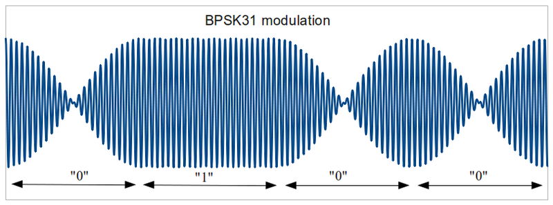
If only the phase was reversed and the amplitude stayed constant, this would be the same as a "key click" in CW, except worse: instead of the amplitude going to zero all of the sudden, it goes to a "negative", in the sense of phase reversal. This would cause "splatter" over a wide band of frequencies. The goal of the design of PSK31 was to use the minimum bandwidth possible for 31-baud data transmission: 31 Hz. (More precisely it is 31.25 baud, or 1/0.032.) To achieve that, the amplitude of the signal is varied smoothly around the phase flip, being zero at the point of the phase reversal, and increasing from there (and decreasing before that point) in a sinusoidal manner. Thus an idle signal is mathematically equivalent to a double-sideband supressed carrier modulated with a 16-Hz sine wave, i.e., two RF sine waves 32 Hz apart, being the upper and lower sidebands. This carefully shaped envelope needs to be achieved, at least approximately, in the CW transmitter for the goal of this project to be achieved.
The way PSK31 modulation is usually done is to generate the signal by computer, in audio rather than radio frequencies, and then feed it into the microphone input of an SSB transmitter. The mathematics of SSB modulation then magically transfer the phase reversals and envelope shape to the new, much higher, frequency. The downside is that SSB rigs are more complicated and expensive. Thus the idea to adapt a CW rig to recreate the correct waveform directly.
The biggest unknown so far is whether it is possible to get a decently clean PSK31 output signal from a CW transmitter, despite it presumably having a class-C final amp. My hope is that many common models may work OK without significant mods albeit at reduced power. If one has to, e.g., use 1 watt at PSK31 instead of 4 watts CW from same rig, that's not really a problem, as it's just one more fun mode made available, and would probably reach just as far, since PSK31 reception can dig into the noise.
My design adds a "bias", or base level of output, to the amplitude modulation, which is adjustable. The idea is to set it so that, at the bottom of the PSK31 envelope dips, just enough RF gets through the driver stage to the final amp that it is right at the threshold of outputting some power, thus effectively moving it to class B. But, as the amplitude increases from there, the final amp output power may not increase linearly enough. That of course would depend on the design of each specific rig, and also on the drive level - I expect it would have to be reduced to a significantly lower power output than in CW mode. If that's not good enough, one may need to further modify the final amp, e.g., adding a bit of DC bias. Another option is to directly AM-modulate the final amp, but hopefully that is not necessary. Yet another potential approach is to modulate the low-level signal, but to measure the final output envelope, compare it to the original AF input envelope, and use the difference to apply (low frequency) feedback to the modulating circuit so as to increase linearity.
There is more than one definition of "linear". In a broadband amp, the actual RF waveform needs to be preserved. That is not the case here - only the envelope (and phase) needs to be preserved. In a CW transmitter the final amp greatly distorts the waveform, but that is OK, since it is returned to a sine-wave (suppressing the harmonics) by a tuned LC network at the output. For PSK, the needed additional linearity is only that the final amp average (say over a millisecond) output power be proportional to its input power. The "bias" in my circuit brings it from class C to class B, i.e., a very small input power already produces some output power. The input-output power curve will of course be a curve, but starting from zero it will then approximate a straight line at first, so if we stay at a low-enough power level it will be "linear" in that sense. What needs to be determined by experiment with actual rigs is how much power can be used before the output signal gets too distorted. It may be helped by adding DC bias to the final amp transistor's base, and also perhaps a small resistor in the emitter.
Alas the theory of class-C RF amplifiers shows that the power output is mostly determined by the conduction duty-cycle of the power transistor (also called conductance angle, a portion of the complete 360 degrees cycle). The amplitude of the input signal affects the duty cycle indirectly, as a stronger input signal starts the transistor conductance earlier in the cycle and ends it later. But at low signal amplitudes, barely enough to cause conductance, the relatively flat top of the sinsoidal waveform may cause a conductance angle that is large relative to the little or no conductance with a slightly smaller input signal. This nonlinearity, at small amplitudes, may have more of an adverse impact on our goal, of a clean PSK31 output, than the compression at large amplitudes. It may be possible to minimize this effect by "pre-distorting" the modulating signal near the zero-crossings.
Reception of PSK signals on a CW rig is straightforward: the audio from a CW receiver only needs to be fed to the computer. It is different from using an SSB rig in that the bandwidth of the receiver is typically narrower, thus fewer signals can be seen at once on the computer screen. A bigger difficulty is aligning the transmission frequency with the received frequency. Using SSB, the (supressed) carrier is the same for both reception and transmission, and by simply clicking on a spot in the waterfall the computer automatically generates the same outgoing audio frequency as incoming, resulting in the same radio frequency. Using a CW rig and an interface like the one I am describing here, the audio frequency has no influence on the transmission frequency, thus this aspect needs explicit handling.
Some rigs are better for the frequency-alignment issue than others. One aspect of a group of many related designs, such as the the SWL SW40+, is that the tx "bfo" is offset from the (separate) rx bfo (by about 800 Hz), while the vfo freq stays the same for tx and rx. And the rx is active while transmitting, generating a "sidetone" via the rx product detector. What this means is that "spotting" the outgoing frequency on the "waterfall" display of received signals is built in! Or one can add a "spot" pushbutton to the rig, powering the mixer/oscillator that generates the tx signal, but not the rest of the tx chain, to be able to "spot" without actually transmitting.
Moreover, once you spot it, can mark the spot on the waterfall (Digipan offers a "mark" feature), and then you can tune a received signal to the right spot in advance of any transmission. But of course only approximately. It would help if one could zoom into a narrower frequency range on the "waterfall". I can't find a way to zoom in Digipan, but in WinPSK it's easy. With, say, a 400 to 1200 Hz range, the "spotting" will clearly show tx/rx alignment within 10 Hz or so. Even in the Digipan display you can easily get it within +-30 Hz or so.
The PSK31 software programs also allow one to "lock" the tx freq on the received one, or not. It is better for the side starting the QSO to determine the frequency, and the other side to "lock". Then if the first side drifts, the other will drift with it, but not vice versa. If an SSB-rig side does not lock, and the other side is a CW tx converted as I suggest, the SSB side will receive a reply off-frequency, but the software should display the text anyway. And, with some software, it would then jump to the new frequency if it is close enough, and will stay there - if the CW-rig side does not re-tune then it is OK. Conversely, if the CW-rig starts the QSO and the SSB-rig locks onto it, all is well?
Thanks to Peter Martinez G3PLX ("father" of PSK31), Onno Hoekstra PA2OHH, Clint Turner KA7OEI, Steven Weber KD1JV, and Dave Benson K1SWL (designer of many popular QRP kits, including the NE4040/SW40, PSK20, and RockMite) for the inspiration from their related past projects, and for current advice on this project, even when their main advice was "not likely to work, but good luck" :-)