Kenwood TR-9000

Recently I picked up a Kenwood TR-9000 all mode 2 meter radio. I got a good price on the radio, but it did have some issues. The previous owner said he sometimes had some distortion on 2m Sideband, and that the finals were a little soft putting out Just at 6 watts. This is going to be used in my truck with a 2 meter halo, and a small FR Concepts amp. The first contact I made with it seemed to have some distortion, and did not go well. I was able to determine that the TX and RX frequencies were not even close. It also had some problems with Carrier Suppression and Mic gain being too high.
After Fixing those issues I was able to test the radio and all was quite well. Later that week I noticed after coming out the the Truck on a warm day the PLL appeared to unlock. Playing with the rotary encoder it would go to the high end of the band but that is it. Also the LCD Display was dim compared to normal. Every time this seem to happen was after the radio got hot, and a good little tap and it was back to normal. Well it finally got stuck and no amount of tapping would fix it for any period of time. The PLL would unlock showing only the 2 decimal points on the digital screen, and it was dim. Playing with the encoder it would only enter high end of the band. When I got it working with a solid tap, the rig would go back, but only on the low band. And the VFO switch would not work. It was time to break into the radio once more!
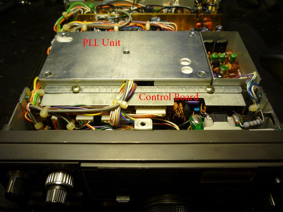
Using a screw driver hand and plastic tuning tool, I began to tap and wiggle around the inside of the radio until I found a spot I could get it to duplicate the problem. In the automotive industry this is the Tap Wiggle Test that we use for intermittent drivability problems. I found that on the edge of the PLL cover, at the right side near the control board screw would do it almost every time. I began to wiggle wires and found that nearly any connector on the control board would cause the issue.

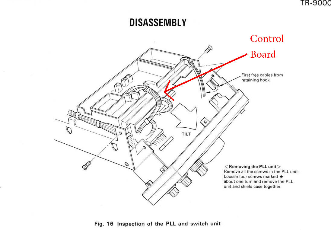
Well unfortunately this means I have to pull the control board. Not terribly difficult, but not an easy task. After the face plate half is loosened the connectors removed, the 4 screws that hole the metal cage in pictured above, the cage and control board will slide out.

As you can see in the picture above the control board is soldered into the shield case. After inspecting the front side of the board I turned it over, and found that all but one of the solder points from the PCB ground to shield case were cracked all the way across. Hummmm is this my problem? Years of thermal cycling and expansion cause the tin shield to expand at a different rate than the PCB. Thus causing the solder joints to fail! Using my digital soldering iron and a large tip, I reflowed the solder and added a little, making sure it was hot enough to provide a proper joint, but not hot enough to delaminate the board. After reassembly and powering on the TR-9000 no amount of tapping can duplicate the problem. It is working great now, and look forward to making some contacts on it while mobile.