Icom 765 PLL Trimmer Repair
Updated 6-Feb-2009 (Minor Windstream server issue)
I have had my Icom IC-765 HF transceiver since 1995. It has logged many (perhaps hundreds)
reliable hours of use. in the spring of 2001, however, it began to develop some quirks. One day while it was receiving
on 30 meters during a particularly busy contest weekend, I started noticing contest activity showing up on
the band. The callsigns were recognized as leaders in the sport of contesting, and I found it odd that they
would be active on this traditionally non-contest band. Another oddity - the signals were weak - weaker
than I would expect from these high power stations. No matter... the contest ended that Sunday evening and
things appeared to return to normal. A few weeks later, while operating on 40 meters CW, the receiver suddenly
drifted 500 hz up over the course of 5 seconds or so, and stayed there. A couple of days after that, everything
received below 10 mhz would become garbled and unintelligable after 30-40 minutes of warmup.
At this point I decided that my trusty 765 was in need of some TLC. A few years ago I had printed out and read
the 765 troubleshooting notes on the Icom web site, and I recalled something about raspy audio ocurring after warmup, and that it sometimes affected
certain frequency ranges. Sure enough, there it was - the dreaded plastic trimmer problem. Being a technician
by trade, and not wanting to sacrifice my radio to the shipping gods for who knows how long, I decided to
attack the problem myself. Here I'll describe for you how I got everything back into shape for just a few dollars
and a few hours of time. The repair is not difficult. I feel that anyone with proper soldering technique and a
decent digital voltmeter can do it. But if you feel squeemish about it, contact Icom Tech Support, and they will do
the proper repairs for you.
What Happened?
What happens is this - the plastic trimmer capacitors in the
PLL (phase lock loop) section of the radio are enclosed in a shielded can. This can also contains several
coils that are covered with a wax to prevent (I presume) vibration. Also in the 765, the PLL board is located
directly below the internal power supply. Now you would think that the heat would radiate up and away
from the PLL unit, but enough heat reaches the board to slowly, over years, cause the wax to flow down
into the trimmer caps. It then seems to eat away at the plastic dielectric of the trimmers, causing the HPL
lock voltage(s) to drift out of acceptable range, which in turn causes all sorts of nasty things to occur.
The raspy audio might just affect a certain range of frequencies, or several ranges, or all. In my case, it just affected everything below 10 mhz.
How do I Fix it?
Only one way - remove the plastic trimmers from the PLL board, and install ceramic replacement
units. We'll go step by step, removing that nasty wax substance (or most of it anyway), and
re-align the vco's according to the service manual. While we're in there, we'll check out a few
other things that may need attention. Time's wasting, so let's get started!
What You'll Need -
Soldering iron - 15-25 watt
Solder wick - to remove solder from traces and shield cans
Soldering gun - here we want something on the order of 100 watt
60/40 rosin core solder (I use Kester Rosin Core 44)
#1 and #2 phillips screwdrivers
Small pair of "nippy" cutters (wire cutters). Smaller the better
Small "jewelers" type screwdrivers, preferrably plastic handles, or similar adjustment tool
Digital voltmeter
Of course you'll also need the replacement trimmer capacitors. The capacitors we'll be replacing
are designated C11, C20, C29, and C37. C11 and 20 are 10pf (picofarad), while C29 and 37
are 7pf. Now... here's where I begin to deviate from the book a bit. First, let me say without
equivocation - I have nothing against Icom service, or ordering replacement parts from them.
However, in this situation I had the parts in hand to do this repair, and they work fine. But -
if you feel that you should get these parts from Icom, by all means do so. Here are the Icom
part numbers to ask for -
Icom part#
4610001130 - trimmers C11 & 20 (order two)
4610001000 - trimmers C29 & 37 (order two)
Now, having said that, you can also get suitable replacements from Digikey. They have to
have leads spaced 4.5 mm apart, be ceramic, and of course be the proper capacitance. I found
these Sprague GKG series ceramic units to be more than adequate -
Digikey part#
SG1029-ND - 3.5-10pf ceramic (white - Sprague pt# GKG10024)
I used this 10pf unit for all 4 caps. Why? Well, C11 and 20 were 10pf anyway, but Icom
recommends in their service notes that C29 be changed from 7pf to 12pf for ease of adjustment.
C37 is(was) 7pf as well, so I figured why not try a 10 there as well? No worries - the 10pf
works just fine for all 4 replacements.
Let's Start
 Begin by laying your 765 on a CLEAN surface - a clean towel to keep from scratching your
radio. So as not to cause any confusion here, throughout this repair, keep the front of the
radio facing you. Remove the little door that covers the adjustments under the top cover, and
set it aside. Remove the screws that hold down the top cover. Remove the top cover by gently lifting
from the rear, then pulling back. Detach the internal speaker lead, noting the direction of the plug, and set the
cover and screws aside. Now turn the radio over, and remove the bottom cover, and set it and the screws aside.
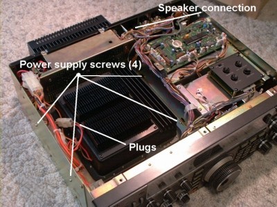
Now flip the radio face up again. Ok, see that big black thing on the left side with cooling fins? That's your 765's
power supply. Our bad caps are below it, so we have to get the power supply out of our way. It's held in by 4 screws - 2 of them go through the left side of the chassis, the other 2 go down on the right side of the power supply into two little
chassis tabs. Remove these screws and unplug the two white interconnect cables going to the supply. Lift the
power supply out, taking care to not damage the cooling fins, and set it and the 4 screws aside.
Begin by laying your 765 on a CLEAN surface - a clean towel to keep from scratching your
radio. So as not to cause any confusion here, throughout this repair, keep the front of the
radio facing you. Remove the little door that covers the adjustments under the top cover, and
set it aside. Remove the screws that hold down the top cover. Remove the top cover by gently lifting
from the rear, then pulling back. Detach the internal speaker lead, noting the direction of the plug, and set the
cover and screws aside. Now turn the radio over, and remove the bottom cover, and set it and the screws aside.
Now flip the radio face up again. Ok, see that big black thing on the left side with cooling fins? That's your 765's
power supply. Our bad caps are below it, so we have to get the power supply out of our way. It's held in by 4 screws - 2 of them go through the left side of the chassis, the other 2 go down on the right side of the power supply into two little
chassis tabs. Remove these screws and unplug the two white interconnect cables going to the supply. Lift the
power supply out, taking care to not damage the cooling fins, and set it and the 4 screws aside.
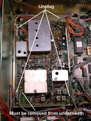
Now what you see on the left side of the radio is the PLL unit. It can be recognized by a few shield cans,
one with 4 access holes in the top. We'll remove this board next. First, notice that there are a few cables that
need to be disconnected. There is one grey coax that cannot be disconnected at the PLL board. It runs under
the chassis to the RF unit.
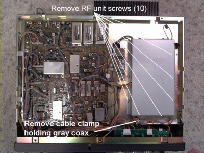
Turn the radio upside down. The RF unit is on the right side, under a shield cover.
Remove all the screws holding the shield cover down and remove it. Notice the grey coax in front of the
RF board that goes through a grounding clamp - this is the coax we need to disconnect. Remove the screw
holding the grounding clamp. Trace the coax over to the RF board, and unplug it from the board. Pull the
coax back through to the top of the radio. Turn the radio right side up again. Now remove the screws holding
the PLL board down, and remove the board. Set the radio aside for now.
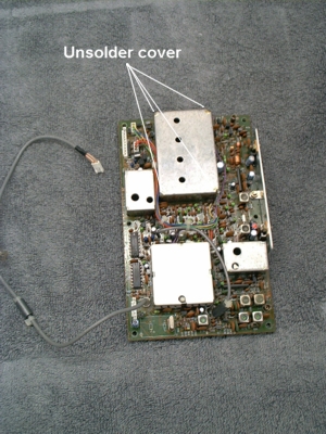
With the PLL board in front of you, again take note of the shield can with the 4 adjustment holes. Our
4 bad caps are under that cover (you can see them through the access holes), so this cover has to be removed.
Using a soldering gun, apply heat to the corners of the shield cover, and use wick to remove the solder
from these areas. It sometimes helps to gently pry on the corners with a small screwdriver while heating.
Take your time, and don't apply too much force on anything.
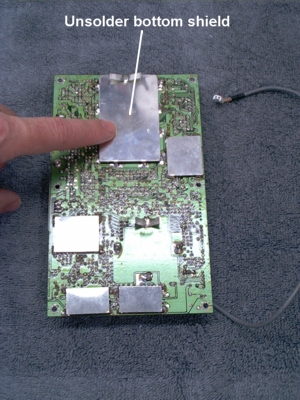
Now flip the board over, and remove the lower shield from the area underneath the shield can. Using
a solder gun, apply just enoough heat to free each tab on the lower shield. Locate the mounting holes
for the 4 caps, and desolder them using a 15-25 watt iron and solder wick.
Now working from the top of the board, pull the old trimmers out (if they didn't fall out already).
See all that tan gummy stuff inside the can? That's the wax that has caused our grief. Using a jewelers
screwdriver, gently dig out the wax from the vicinity of the trimmer mounting holes. If there are
signs of wax that may later migrate down into the area of the caps later on, go ahead and gently remove it,
taking care to not distort any coils or break any other components. If the wax is fairly solid, it sometimes
helps to apply heat from a blowdryer while scraping.
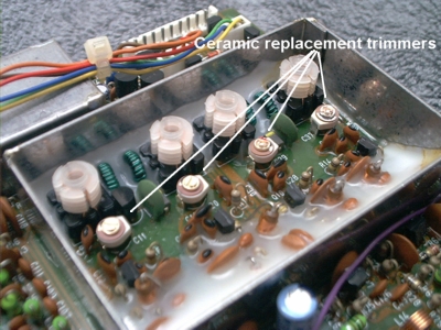
After the areas have been cleaned, install the new trimmers in their proper positions and solder them in.
Be sure to clip the leads flush with the board underneath so they don't touch the lower shield. At this point
inspect all the traces underneath the shield can for possible cold joints and touch-up with a little solder as
nessesary. Icom recommends doing this before re-attaching the lower shield, so I suspect they have seen
problems with solder joints here - so it's best to give it a good look-over.
ReassemblyRe-attach the lower shield to the underside of the PLL unit. Re-attach the top shield can cover (the one
with 4 holes), taking care to orient the cover so you can see the trimmers through the adjustment holes, and solder the corners. Mount the PLL unit back into the chassis, taking care to not pinch
any connecting cables. Re-attach all connectors. Re-route the grey coax to the RF unit, attaching the grounding
clamp. Attach the coax to the jack on the RF unit. Replace RF unit shield cover.
With the radio right side up, connect the plugs to the power supply, but do not put the supply back in
the radio yet. You can lean it up against the left side of the chassis for now. Plug the AC cord in, and attach
some sort of antenna (dipole, piece of wire, whatever). Turn the radio on. Don't worry if you can't receive
anything. You probably won't right now, as the new trimmers need to be adjusted.
AlignmentRemember - radio is right side up, facing you.
The Icom service manual says to use an oscilloscope to make these adjustments, but I obtained
excellent results with a good digital voltmeter (DVM). Attach the
dvm ground lead to the chassis. Attach the positive lead to resistor R6 on the PLL board. R6 can be found
immediately to the left of the 4-holed shield can that we worked on - it's marked on the board. Next we'll
make a series of adjustments to our new trimmers, working from the front trimmer (C11) to the back (C37).
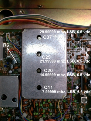 Set frequency to display 7.99999 Mhz, and select LSB mode. Adjust C11 (the front adjustment hole) for a
reading of 6.5 volts DC on the dvm.
Set frequency to display 7.99999 Mhz, and select LSB mode. Adjust C11 (the front adjustment hole) for a
reading of 6.5 volts DC on the dvm.
Set frequency to display 14.99999 Mhz, LSB mode. Adjust C20 (2nd from front) for a
reading of 6.5 volts DC on the dvm.
Set frequency to display 21.99999 Mhz, LSB mode. Adjust C29 (3rd hole back) for a
reading of 6.5 volts DC on the dvm.
Set frequency to display 29.99999 Mhz, LSB mode. Adjust C37 (rear) for a
reading of 6.5 volts DC on the dvm.
Now check the voltage at the following 4 frequencies to ensure that it is more than 2 volts DC -
0.03000 LSB
8.00000 LSB
15.00000 LSB
22.00000 LSB
Together...AgainRe-install the power supply, taking care to not pinch any of the leads or damage the heat sink fins. Now
would also be a good time to inspect the big white power supply plug for any signs of damage. Several 765 owners have had trouble with this plug, again due to heat. The plug will turn brownish in color, and become brittle. Contact
Icom Service for a proper replacement.
Attach the top and bottom covers, speaker plug, and top access door. Enjoy!
Rich, N8UX.
The author assumes no responsibility whatsoever for damages - absolutely nothing
is expressed or implied here. Perform this repair at your own risk. If you feel this repair is beyond your ability, please contact Icom Service for repair/parts.
The N8UX Web is © copyright 1996-2009 Rich Dailey, N8UX. All
rights reserved.
Void where prohibited. Keep hands and feet inside the vehicle at all times.

