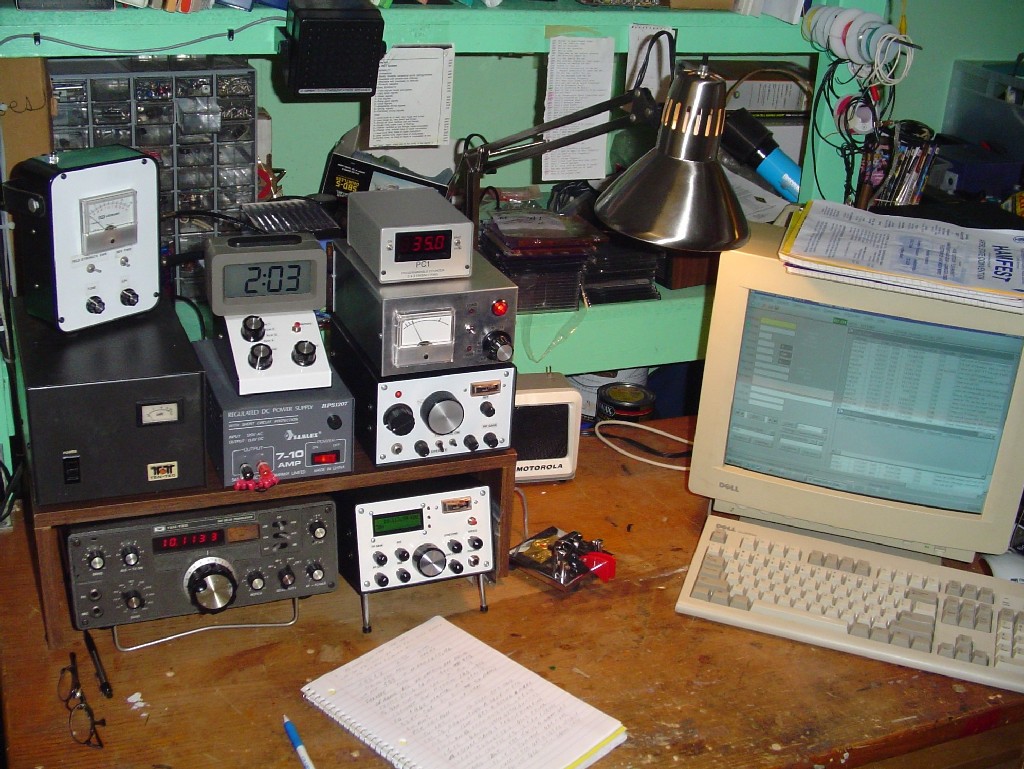
The Shack - January, 2008
The Shack - July, 2007
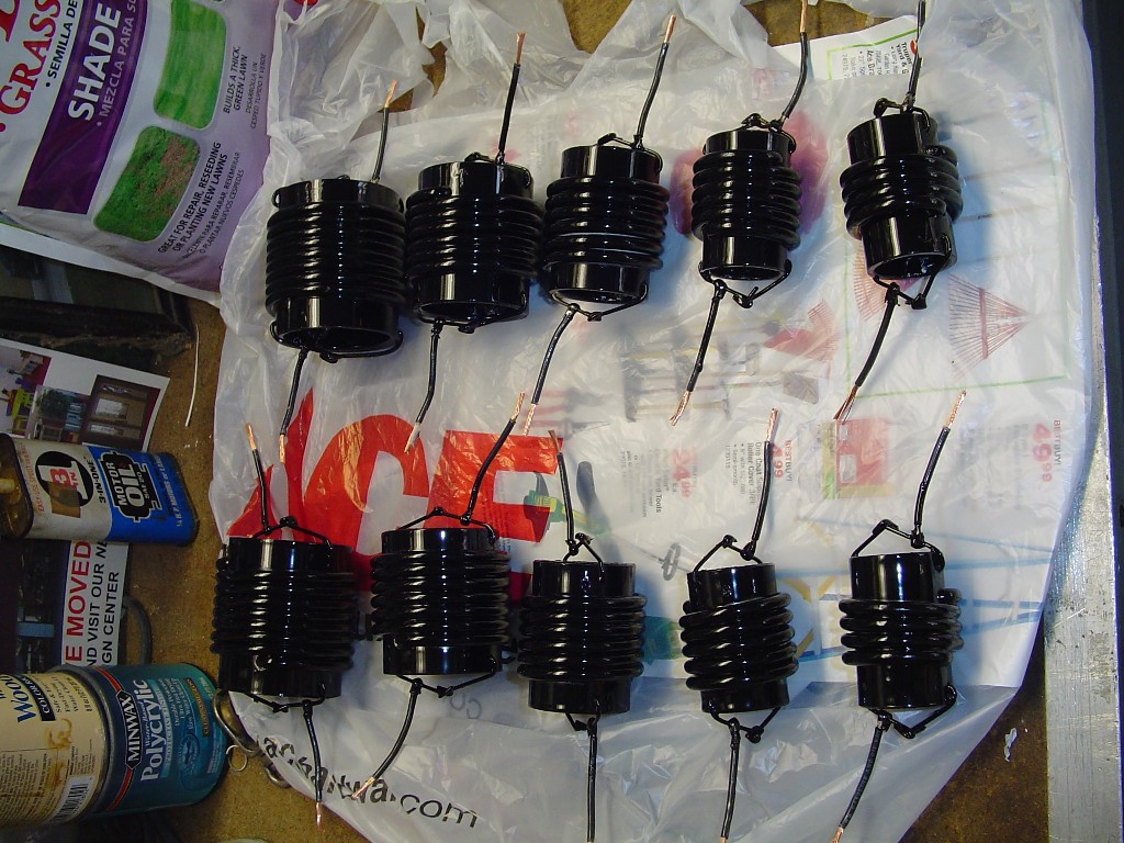
In my first multiband antenna effort I duplicated the "Attic Coaxial Cable Trap Dipole for 10, 15, 20, 30, 40, and 80 Meters" by John DeGood, NU3E. This first picture above shows final tweaking of the resonant trap frequencies before cementing the cable on to the form using an EICO grid dip oscillator loosely coupled to the trap for the minimum dip and an S&S frequency counter.
I was getting pretty good at making these :) I found it best to build my traps with a small amount of extra inductance and then spread the coils to reduce inductance that increased the resonant frequency to target - alot easier than adding cable after winding! I used super glue to adhere the coils to the PVC. A couple of drops at each winding wicked nicely all around the circumference. My traps were then painted black to improve "Curb appeal".
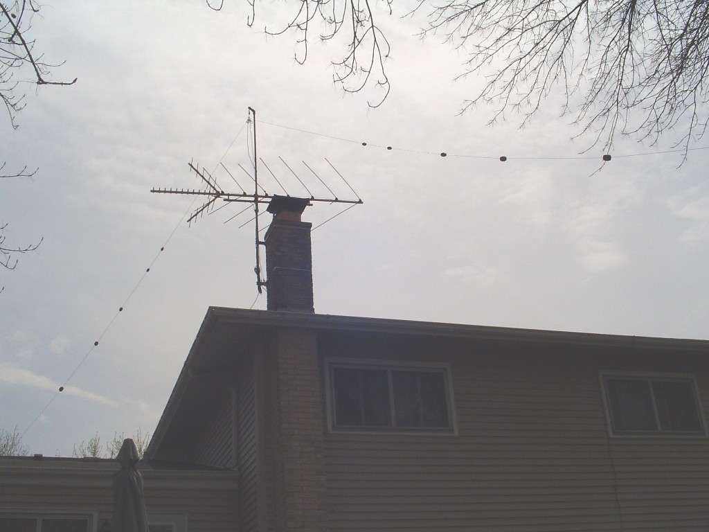
This antenna DID work, although I did not make any contacts with it on 10 or 15 meters due to band conditions. I just did not receive signal reports on 30 or 40 meters that were near comparable to my old monoband dipoles. Obviously the mounting location was not helping things with the TV antenna and gutters right below . With 10 traps, I believe I learned about antenna losses first hand in this project. Being a QRP guy I think the 10 traps ate my little signal for lunch. Still a really good antenna, documented first class by Mr. DeGood, and a very reproducable project. The amount of bands it covers in such a small space with such a good match is quite an achievement IMO. If I was not a QRP operator - this antenna would still be up. I may resurrect it as I still have the traps!
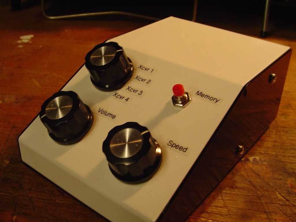
This
is another Norcal keyer kit. This time its built into a box with all
the controls panel mounted. I needed a box like this since I never
installed a keyer in my Oak Hills 40 meter rig, and the Ten Tec Delta
from 1981 required a keyer as well. Then there is the fact that I am
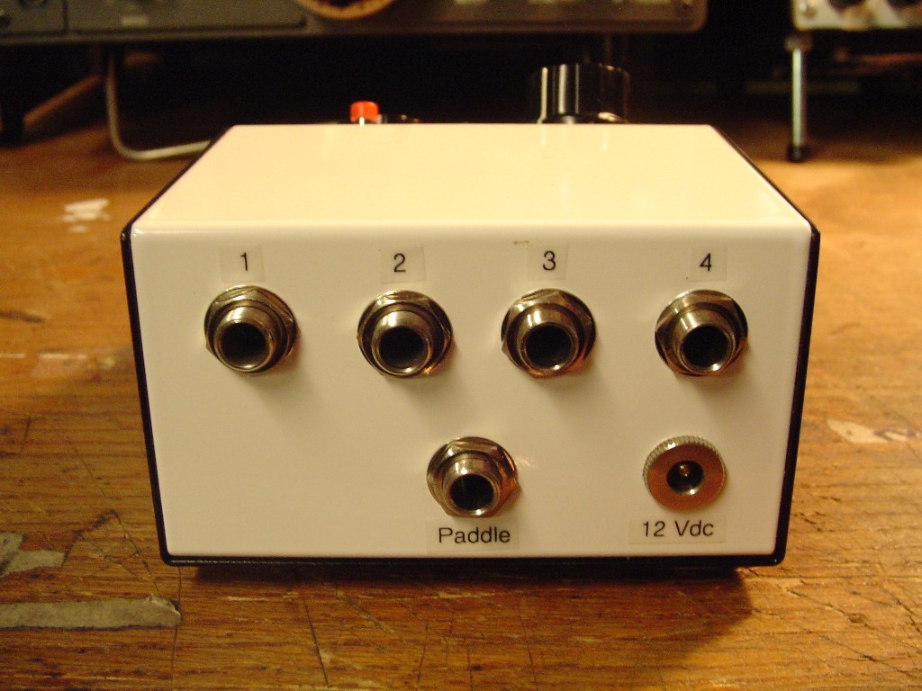
only going to use one paddle for all my rigs. This box can switch the
paddle between up to four rigs (See below). It also can provide a
sidetone
for my Oak Hills 40 meter rig when using it on speaker - since that rig
has too weak a sidetone volume for speaker operation IMO.
My five band, remote tuned vertical antenna (Base view)
Original Tuner
Box
* Updated Tuner Box *
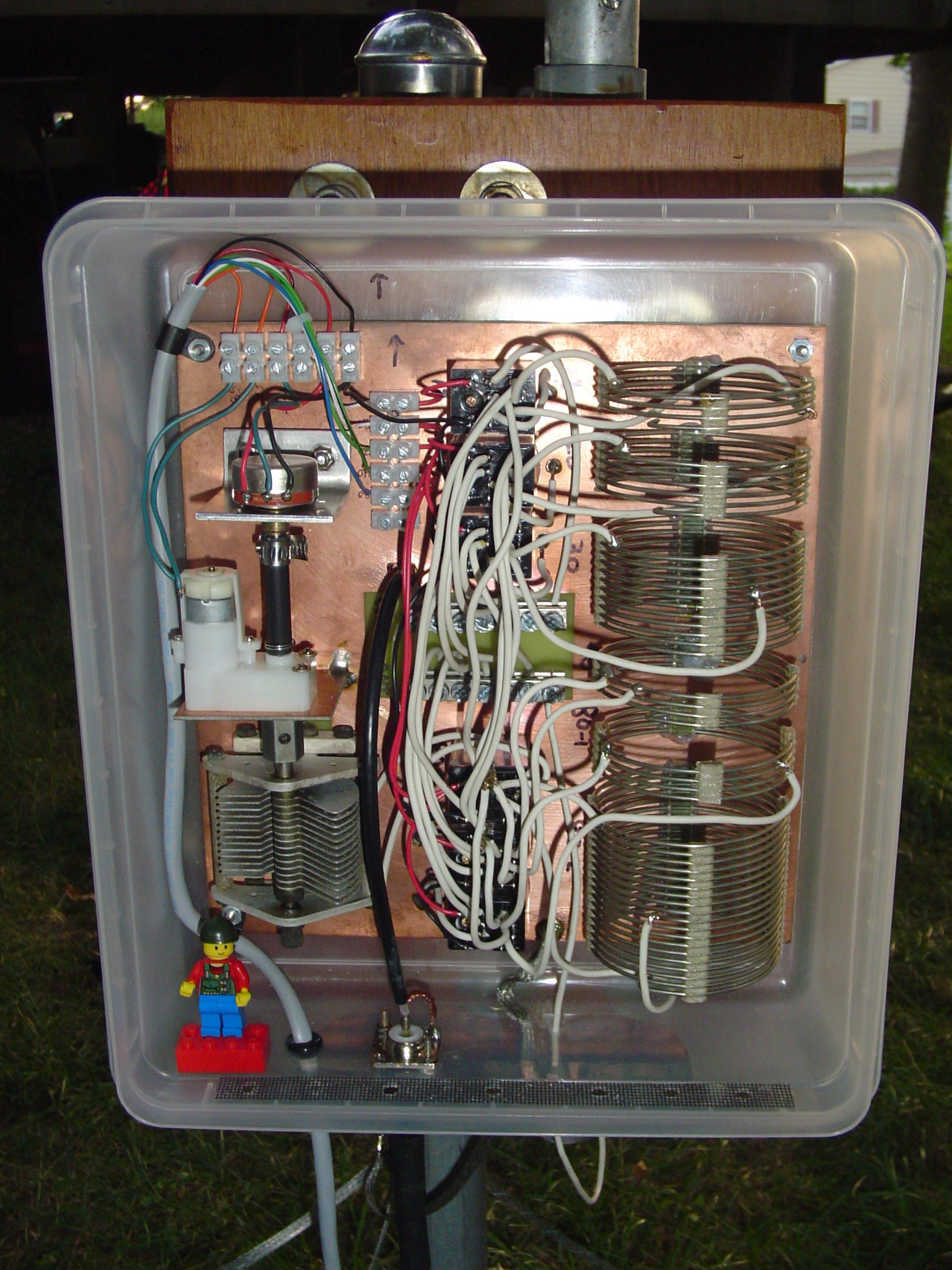
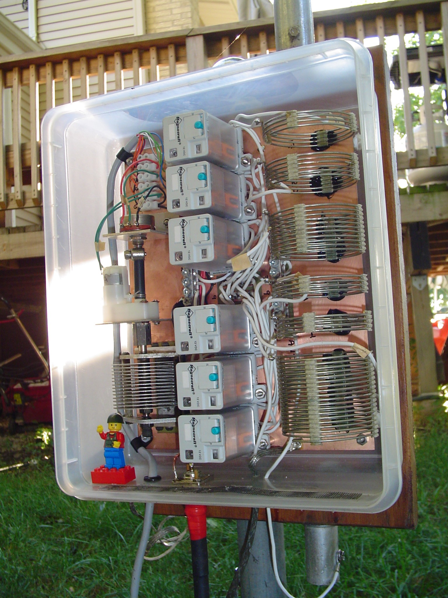
This is the remote tuner box for my 34 foot aluminum vertical antenna. I decided to base the antenna on a 40 meter, 1/4 wave - since I enjoy 40 meter operation alot.
The whole multiband vertical project was based on the methods and ideas of N3OX published at his marvelous website. I had the remnants of my old GAP Challenger and also picked up an old aluminum CB antenna at another hamfest. This would be the raw material for the vertical.
The standard formulas told me 33.5 feet for 7.040 Mhz., but EZNEC insisted on 34.5 feet and had the graph to prove it. Maybe it was the 'stepped diameter correction factor', but I thought that using tubing would make an antenna shorter. Anyway I decided to go with the EZNEC numbers.
After laying out the antenna for 7.040 Mhz in the EZNEC demo, I followed the instructions at N3OX's website for using L_tuner.exe for the
L network components, and then used SOLNOID_3.exe to figure the inductor sizing. I picked up a 2.5 x 9 inch airdux coil at the hamfest for $1, and segmented it per the software. The relays and gearmotor were ordered online, and I finally got to use one of the air variable caps out of the junk box that was as old as I am!
The main "Coax Bus" and "Ant Bus" lugs are house service panel neutral bus bars from Home Depot. The smaller terminal strips you may recognize from Radio Shack. My only gripe about this gear motor is that the output shafts have flats and are metric - this layed to waste all of my old 1/4" couplings, shafts, verniers and adapters. I finally settled on the stiff, black, plastic shipping tube that a childs' 'glow necklace' is packaged in for the coupling shaft from the position pot to the gearmotor. Fight metrics with metrics ;)
The entire board is enclosed in a Martha Stewart food container for weatherproofing and ventilated with holes and screening at the bottom.
* Update 09/07* After about two months of operation, significant corrosion was evident in the tuner box on the hardware. Probably a combination of disimiliar metals and the hot and humid box being mounted one foot off the ground. I started to have trouble with the relay contacts conducting poorly as a result. Cycling the relays helped sometimes, but gradually would not improve the operation (SWR) at all. After attempting to remove relays for contact cleaning it became apparent that my "Hardwiring" of the original relays would be unacceptable for future maintenance. I decided to replace the whole set Sept. 2007 with heavier duty relays of plug in design. The new units are Magnecraft 3PDT 15A instead of the 4PDT 5A old ones. These were reasonably priced and available with the sockets at Mouser. The contacts are also gold flashed (Should help on the corrosion) and of course they are now easily unplugged and removable for cleaning should it be necessary.
EZNEC shows the main lobe angles as follows:
80m 27 deg
40m 26 deg
30m 24 deg
20m 19 deg
17m 16 deg (Lobe is just starting to deform)
On 15m the antenna suprisingly should require no matching to 50 ohm coax, however the launch angle jumps up to 46 deg. So this band was not included. With the current low in the sunpot cycle though, I have time to come up with somthing else for the higher bands anyway. I do not have any plans to install 80m radials for it at this time. Whatever I can get on 80m right now - I get. However I have now been able to contact Michigan and West Virginia from my Chicago area QTH on 80m with 5w during the summer's high QRN - so good enough for me. The signal reports on 20, 30, and 40 meters so far are comparable to my other monoband antennas running 5w, even a couple of Euros on 30m - so I am pleased. Regardless, I really learned alot on the project making it very worthwhile anyway.

This is the remote tuner control head. I had some trouble finding out
after 3 weeks that my plus and minus 5V power supply commercial board
was on "Backorder". Although I had already constructed the N3OX servo
control circuit, I did not want to wait another 2 weeks to order the
minus 5V regulator online and then begin construction of the suitable
power supply. So my 'plan B' was just a SPDT switch firing + 5V to the
gearmotor.
I also used an idea by W0RPV published in Volume 2 of the ARRL Antenna Compendium "A Remotely Controlled Antenna Coupler". He used a pair of LED's in parallel with 3 ohm resistors in each feed line to the motor to indicate when the motor stalled after hitting a stop. The LED's illuminate during high current draw. I had to experiment with the resistor values for my installation - but the idea worked out fine.
I used a 12V/1.7 A power supply, neon lamp, and panel meter from the junk box. A LM317 regulator board for the +5V was then built and added inside the box. The 12V supply feeds the LM317 circuit, and is also for switching the relays through the rotary switch. The panel meter face was replaced with photo paper and marked after finding the best match position of the air variable capacitor on the different bands.
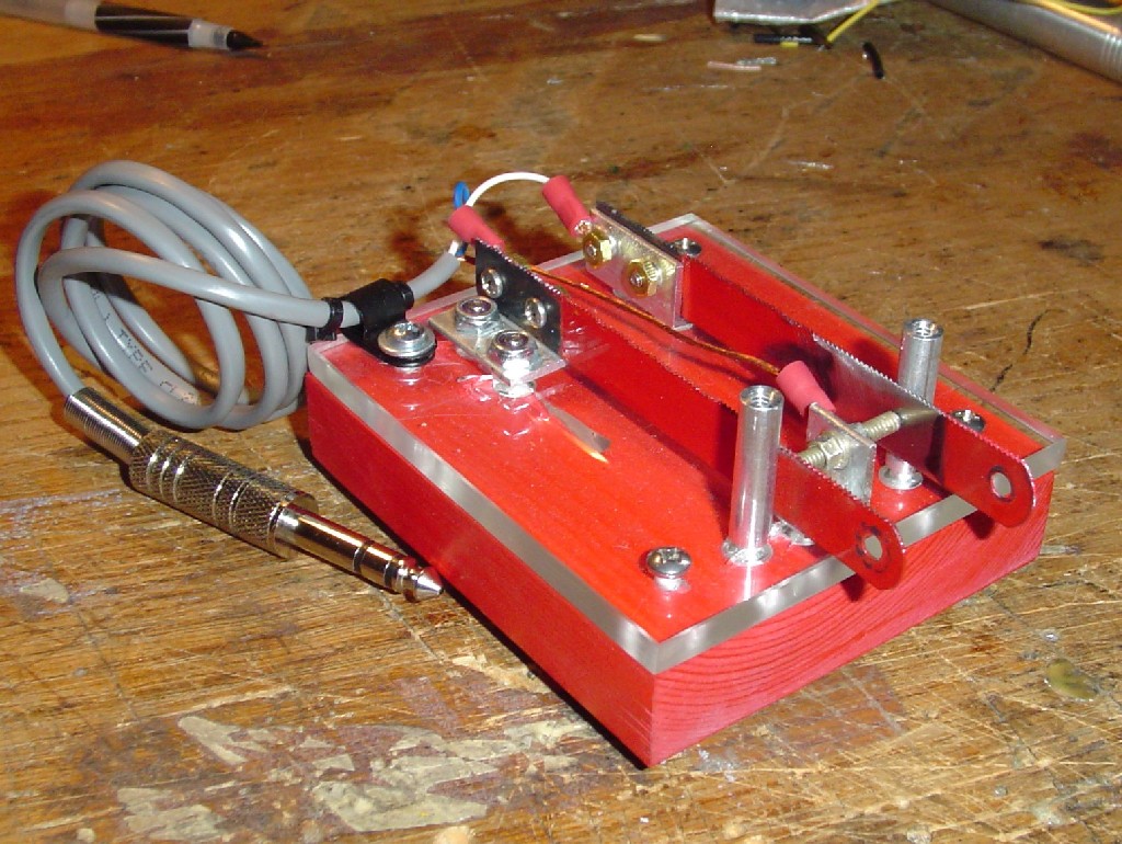
I whipped this homebrew paddle up using some hacksaw blades after
reading an article over at Eham.net. It was good enough to start
practicing paddle moves on.
LINKS:

The American Morse KK-2 portable paddle kit.

- Eham
- QRZ
- Ham Universe
- K8IQY "Manhattan Madness" Projects Page
- Norcal QRP Club
- American QRP Club
- Oak Hills Research
- Seven Oaks Art
- Amateur Radio Clip Art
