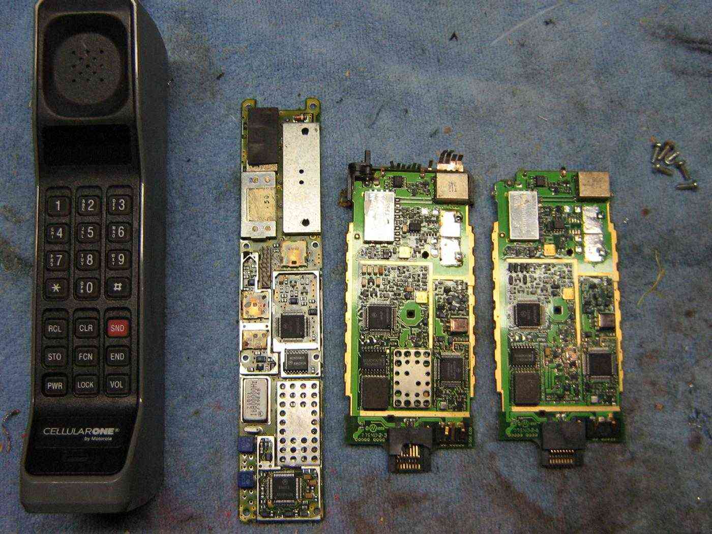
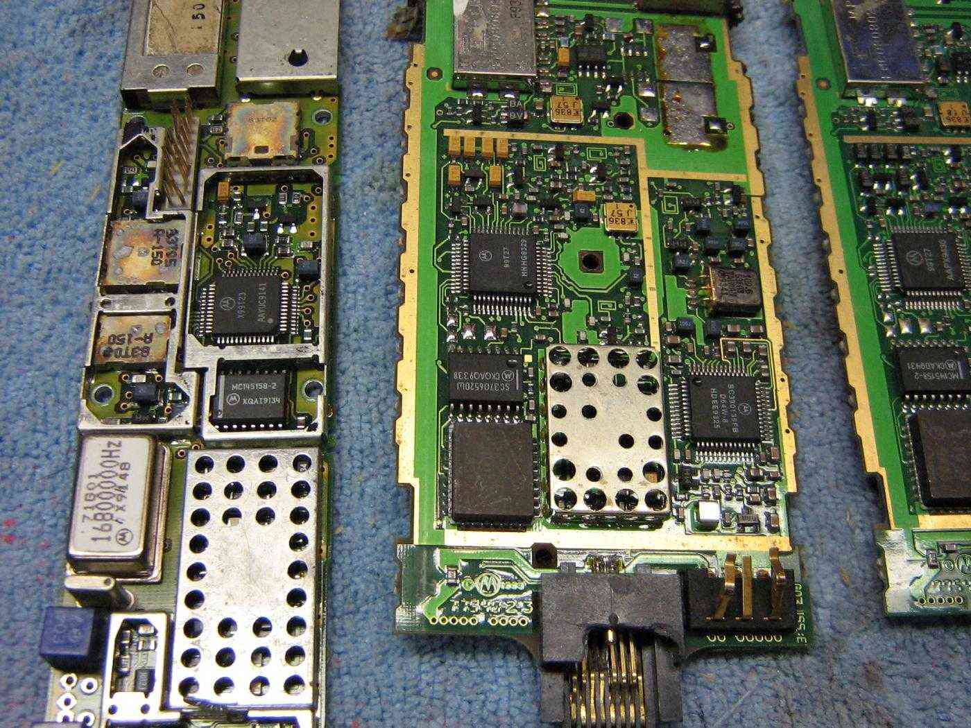
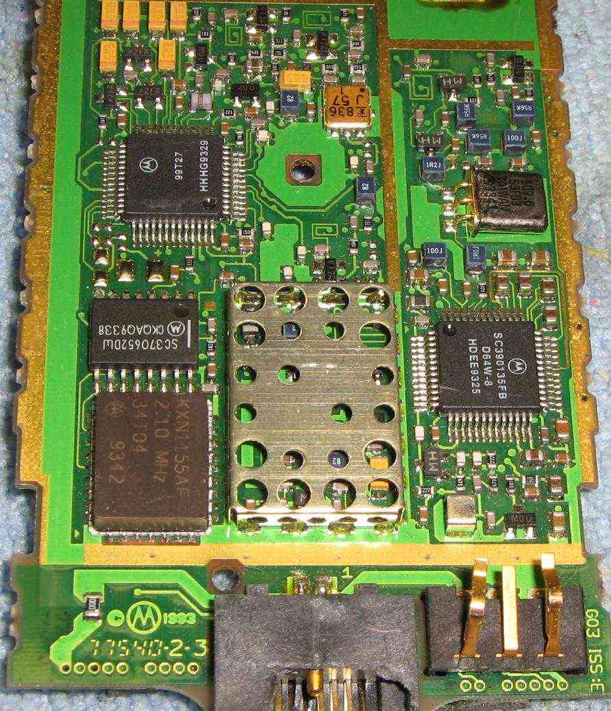
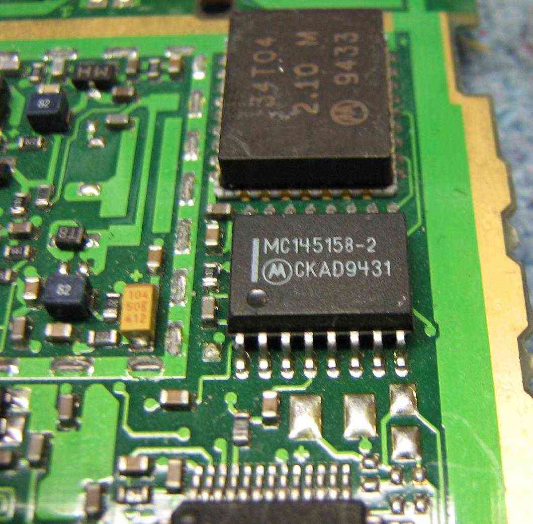
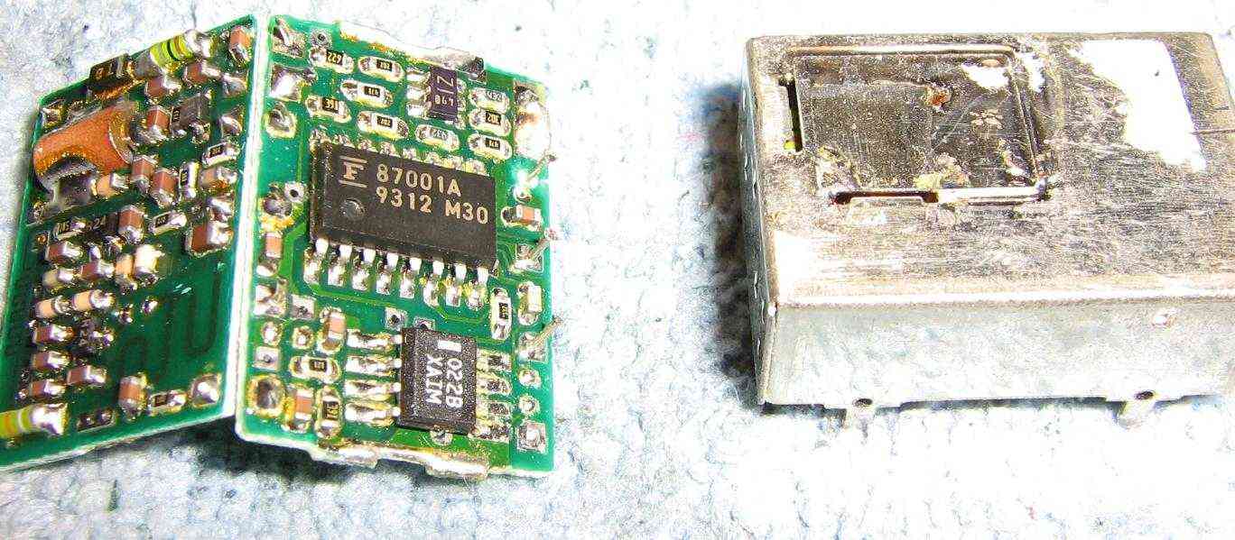
The Motorola MC145158 is a dual-modulus, serial-input PLL frequency synthesizer which is commonly used in older Motorola cellular phones. Refer to the MC145158's datasheet for the nitty-gritty technical details. The MC145158 is no longer manufactured, but it does pop up from time-to-time in surplus electronic stores. Digi-Key used to carry it, part number MC145158DW2-ND. The Fujitsu equivalent is the MB87001A, which is very common in old Japanese-manufactured (Uniden, Toshiba, etc.) cellular phones. The programming of the MB87001A is the same as the MC145158, but the technical specs to the MB87001A are slightly different.
The maximum input frequency for the MC145158 is only around 20 MHz when run at +9 VDC. It drops to around 15 MHz at +5 VDC. The R-Counter reference frequency divider range is between 3 and 16,383. The N-Counter can be between 3 and 1,023. The A-Counter dual-modulus range is between 0 and 127. When using an external dual-modulus prescaler set to /64 (divide-by-64), such as a Motorola MC12022 or Fujitsu MB501, don't exceed a value of 63 for the A-Counter.
The MC145158 is designed to be programmed via a microcontroller using a standard serial-input data stream. The MC145158 has pins for the shift clock (CLK, pin 9), serial data input (DATA, pin 10), and latch enable (ENB, pin 11). These three lines control how and when the PLL is programmed. Once programmed, all the counter's values will remain programmed until power is removed from the circuit. Also, the counters must be programmed Most Significant Bit (MSB) first.
From the MC145158's datasheet:
CLK, DATA
Shift Clock, Serial Data Inputs (Pins 9, 10)Each low-to-high transition of the CLK shifts one bit of data into the on-chip shift registers. The last data bit entered determines which counter storage latch is activated; a logic 1 selects the reference counter latch and a logic 0 selects the /A, /N counter latch. The data entry format is as follows:
END
Latch Enable Input (Pin 11)A logic high on this pin latches the data from the shift register into the reference divider or /N, /A latches depending on the control bit. The reference divider latches are activated if the control bit is at a logic high and the /N, /A latches are activated if the control bit is at a logic low. A logic low on this pin allows the user to change the data in the shift registers without affecting the counters. ENB is normally low and is pulsed high to transfer data to the latches.
What this means, in English, is that to program the counter data into the MC145158, you need to set the voltage on the DATA pin to +5 volts for a logic 1, and 0 volts (ground) for a logic 0. You'd then raise the CLK pin to +5 volts, from it's initial value of 0, then quickly bring it back to 0 volts. Do this 15 times to load the R-Counter value (14 bits, plus one control bit). When finished, raise the ENB pin to +5 volts, from it's initial value of 0, then quickly bring it back to 0 volts. The data is permanently latched into the counters. To load the /N and /A counters, do the same again, but you'll need to load 18 bits (17 bits, plus one control bit).
MC145158-to-PIC16F84 pin connections for the example MC145158 loader code which will be used:
| MC145158-to-PIC16F84 Connections | |||
|---|---|---|---|
| MC145158 Line | MC145158 Pin # | 16F84 Port | 16F84 Pin # |
| DATA | 10 | B0 | 6 |
| CLK | 9 | B1 | 7 |
| ENB | 11 | B2 | 8 |
The following is an easy-to-follow example using PICBasic and a Microchip PIC16F84. The R-Counter will be programmed with a value of 2600, the N-Counter with a value of 133, and the N-Counter with a value of 7:
                  ' Load /R counter with a value of 2600, MSB first
Gosub zero        ' 8192
Gosub zero        ' 4096
Gosub one         ' 2048
Gosub zero        ' 1024
Gosub one         ' 512
Gosub zero        ' 256
Gosub zero        ' 128
Gosub zero        ' 64
Gosub one         ' 32
Gosub zero        ' 16
Gosub one         ' 8
Gosub zero        ' 4
Gosub zero        ' 2
Gosub zero        ' 1
Gosub one         ' CONTROL, R = 1

Gosub enable      ' ENABLE

                  ' Load /N counter with a value of 133, MSB first
Gosub zero        ' 512
Gosub zero        ' 256
Gosub one         ' 128
Gosub zero        ' 64
Gosub zero        ' 32
Gosub zero        ' 16
Gosub zero        ' 8
Gosub one         ' 4
Gosub zero        ' 2
Gosub one         ' 1
                  ' Load /A counter with a value of 7, MSB first
Gosub zero        ' 64
Gosub zero        ' 32
Gosub zero        ' 16
Gosub zero        ' 8
Gosub one         ' 4
Gosub one         ' 2
Gosub one         ' 1
Gosub zero        ' CONTROL, N & A = 0

Gosub enable      ' ENABLE
End

zero:
        Low 0     ' Load 0 on pin 6 (Port B0 - DATA)
	High 1    ' Bring pin 7 high (Port B1 - CLK)
	Low 1     ' Then back low
        Return
one:
        High 0    ' Load 1 on pin 6 (Port B0 - DATA)
        High 1    ' Bring pin 7 high (Port B1 - CLK)
        Low 1     ' Then back low
        Return
enable:
        High 2    ' Bring pin 8 high (Port B2 - ENB)
        Low 2     ' Then back low
        Return
Here is an example of PICBasic code which uses the SHIFTOUT command. It's operation will be much faster, and will not use as much memory in the PIC16F84. The R-Counter will be programmed with a value of 2600, the N-Counter with a value of 133, and the N-Counter with a value of 7:
RVAL        VAR       WORD
NVAL        VAR       WORD
AVAL        VAR       BYTE

RVAL = 2600
NVAL = 133
AVAL = 7
                          ' SHIFTOUT data, clock, mode, [var\bits]
                          '
SHIFTOUT 0,1,1,[RVAL\14]  ' Load /R counter with a value of RVAL (14 bits), MSB first
SHIFTOUT 0,1,1,[1\1]      ' CONTROL, R = 1

High 2                    ' Bring pin 8 high (Port B2 - ENB)
Low 2                     ' Then back low

SHIFTOUT 0,1,1,[NVAL\10]  ' Load /N counter with a value of NVAL (10 bits), MSB first
SHIFTOUT 0,1,1,[AVAL\7]   ' Load /A counter with a value of AVAL (7 bits), MSB first
SHIFTOUT 0,1,1,[0\1]      ' CONTROL, N & A = 0

High 2                    ' ENB
Low 2
End
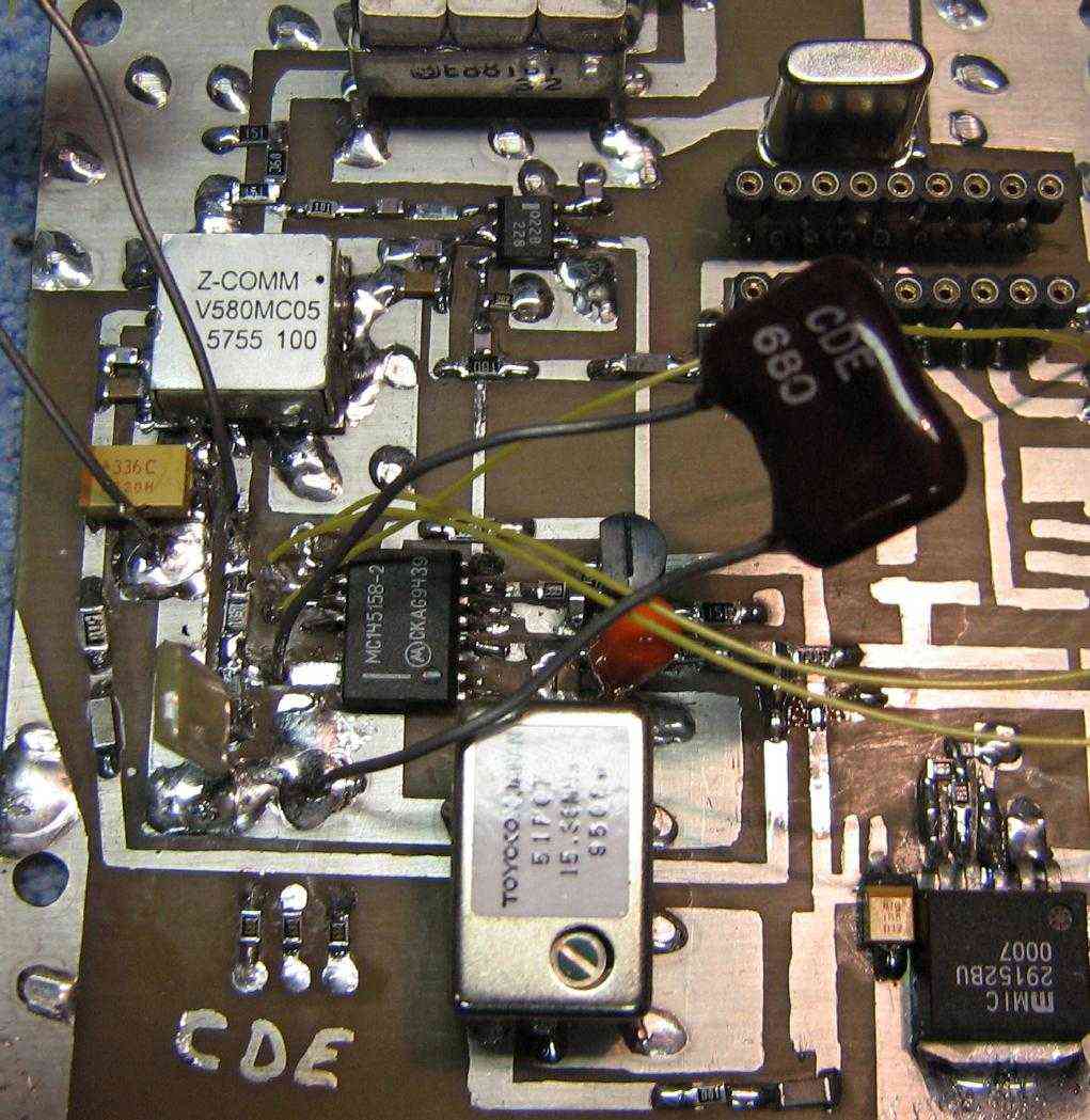
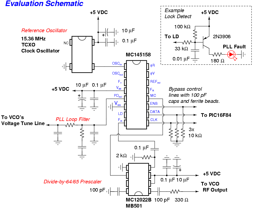
Here is some example PICBasic code which will continuously increment the /N and /A counters on a MC145158. It was originally designed to be a synthesized cellular phone jammer, but the combination of PICBasic and the PIC16F84 proved to be much too slow. The reference oscillator for this code was 15.36 MHz, with a R-Counter of 512. This gives a reference frequency of 30 kHz, standard for cellular phone applications. The MC145158 used an external MC12022B dual-modulus prescaler, set at /64. The rest of the PLL math looks like:
Reference Oscillator : 15.36 MHz
 Reference Frequency : 30,000 Hz
    /R Counter Value : 512
    /N Counter Value : 452 to 465
    /A Counter Value : 0 to 63
  Target Frequencies : 867.84 MHz to 894.69 MHz

Example

(452 * 64) + 0 = 28,928
28,928 * 30,000 = 867.84 MHz

...

(465 * 64) + 63 = 29,823
29,823 + 30,000 = 894.69 MHz
DEFINE SHIFT_PAUSEUS 1

NVAL        VAR       WORD
AVAL        VAR       BYTE
IVAL        VAR       BYTE

SHIFTOUT 0,1,1,[512\14]  ' Load /R counter with a value of 512 (14 bits), MSB first
SHIFTOUT 0,1,1,[1\1]     ' CONTROL, R = 1

High 2                   ' ENB
Low 2

' Load /N counter with a value of NVAL (10 bits), MSB first
' Load /A counter with a value of AVAL (7 bits), MSB first
' CONTROL, N & A = 0
' Loop 50 times

For IVAL = 0 to 50
  For NVAL = 452 to 465
    For AVAL = 0 to 63
      SHIFTOUT 0,1,1,[NVAL\10]   ' /N Counter
      Shiftout 0,1,1,[AVAL\7]    ' /A Counter
      Shiftout 0,1,1,[0\1]       ' CONTROL
      High 2                     ' ENB
      Low 2
    Next AVAL
  Next NVAL
Next IVAL
End