|
Atenuation is controlled by 9 bi-stable 74HC04 based flip-flops. Schematics of one circuit:
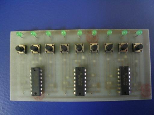
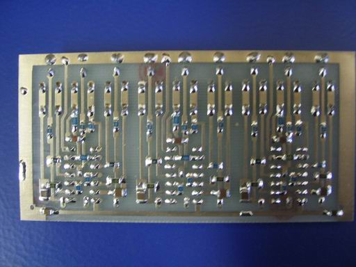
Outputs 1,2,3 go to the atenuation board. As AT220 are controlled by negative voltage signals pin 14 is grounded and pin 7 is fed by -5V. Atenuation is signaled by LED. PCB:
Dimensions are 100 x 50 mm. This is bottom view. From this side there are all SMD components, condensers and IC are placed on the oposite side.
Outputs to AT220 go from pins 8, 12 and 6 (wire bridged under IC). Overall view:
|


