The switch I made to my first Alinco DX-70.
(TOP of page)
And I have used until marts 2007.
The 8-pin microphone connector is for a Alinco DX-70. Therfore the pins is named with ther function.

How it really looked:
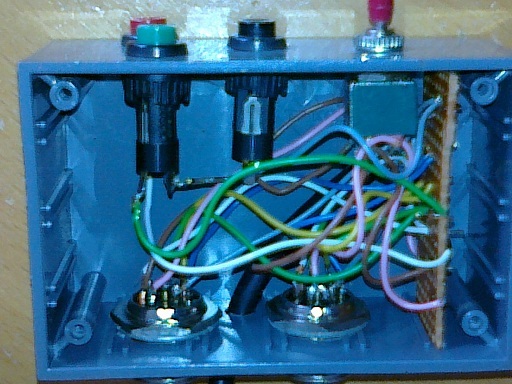
It was placed in small plastic box. On the back side. I drilled a small whole for a cable to connect to the microphone on the radio.
And 2 wholes for microphone plugs.
On the front I drilled 4 wholes, 3 of them for push bottoms:
S2 for DOWN - red
S3 for UP - green
S4 for PTT - black
The last whole for the S1 is a ON-ON stereo switch. To make the change between PC-interface and the microphone.
(TOP of page)
All in a "box". Here is a combination off the switch-box and PC-TXRX interface.
(TOP of page)
I did make some cables to connect the pc and interface. Thise uses 3,5mm mini jacks, that fits into the PC soundcard. That type was on the interface. Generel discription of cabels and connectors beeing used:
REMEMBER the connector to the pc must NOT have a ground connection to the interface chassis!
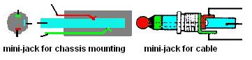 The plugs as drawn.
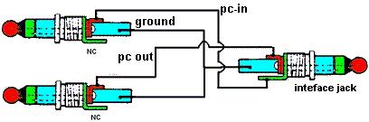 The soundcard to interface cable.
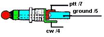 The pc-comport to interface cable.
The cable connecting the mic to TXRX is in the 1. version fitted to the interface with a 7pol mic-plug (it can with old UHF x-tal radio. I used asub25 in the next version. Giving room for other connectors, without having to drill new holes.
The first "combi-box":
This time I took and old UHF 3-channel transceiver. Rip it of its parts apart from the speaker. Then I mounted a piece off vero-board as base for the component and different wires.
This is a simple version, where the TXRX ist connected to either the microphone or the interface.
Theres only added the up/down function.
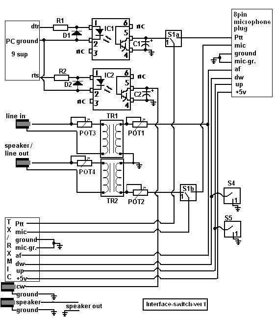
R1 = R2 = 1.5 kOhm 1/8W. POT 1,2,3 and 4 is 0-47kOhm. D1 =D2 =plain led's. C1 and C2 are just some small "blue" tantals. Used to "kill" noise on the output. S1 is a stereo on-on switch and the S4 and S5 is PUSH-buttoms IC1 = IC2 is 4n36. The interface was build into an old UHF x-tal radio. And used an excisting mic pæug at the back. |
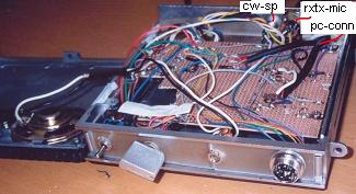
From above.
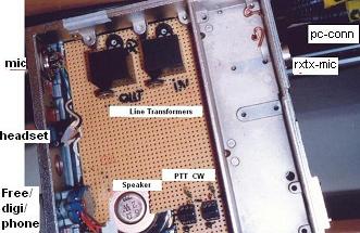
This is the buttom view.
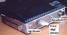
The closed interface seen towards the front.
In the next version I added some extra switches.
One added "bonus" is the switching of the microphone to the input terminal on the soundcard. In that way making it easy to recording "your-voice" for "CQ-calls" and more.
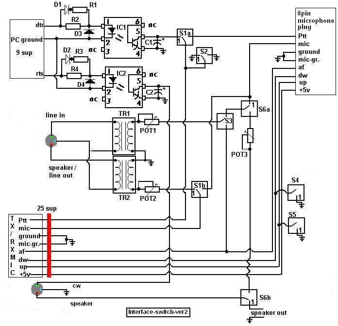
To do that the switches S3 and S6 where added.
S3 switches the PC-input from the "af" in the mic.-plug on the TXRX to the "bonus".
The S6 is the "bonus". That makes it up to you to choose between the speaker-out or your voice from the microphone.
So it is possibel to use the speaker-jack on the TXRX as "af"-signal for the PC-input. If your TXRX doesn't have that signal in the microphone plug.
The expanded version.
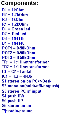 | This is comments to the listing of components used. The Resistors R1,r2,R3 and R4 is 1/8 watts. The Diodes D1 and D2 is plain led's. The POT are ordinary potentiometers. TR1 and TR2 are 600 Ohm line transformeres. C1 and C2 are just some small "blue2 tantals. Used to "kill" noise on the output. The S2 is a switch with the funtions it can hold itself "on" in one position, And the other "on" possition you have the hold. It workes like "lock" and "ptt" on deks top microphones. The fat-RED-line is a sub25 connector connecting the MIC on the TXRX to the interface. The PC-COM is connected to stereo jack. The line-in and line-out is also joined at a stero-jack. The speaker out and CW-in on the TXRX is connected via stereo-jack to. |
Her is an exampel of the front-panel with 6 switches and 2 diodes mounted.
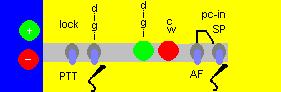 From the left: Up (S4) and down (S5) push buttoms. The Push To Talk / lock switch (S2). Swiching between digimode or phone (S1). The digimode PTT on diode (green) The CW key indication diode (red) PC-in section: Switch (S6) between AF or the signal from either speaker or mikrophone (S3). |
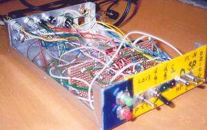
A view from front to back.
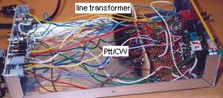
From the side it's clear that the wiring is a job that takes some time.
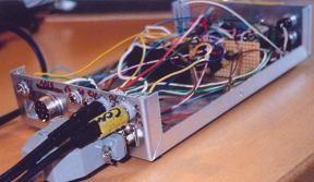
This a view off the back. Where all the plugs are mounted.
Now some hints on using the switches:
For maximum talk power: S1 placed at phone (Down), S6 (UP) towards S3 (UP) to SP (UP)
For maximum recording of Youre voice: S1 (down), S6 (UP) and S3 (down) to microphone.
(TOP of page)