QRSS RECEIVER FOR 40 METERS
(2020)
KLIK HIER VOOR DE NEDERLANDSE VERSIE

The 40 meter QRSS receiver. On the left the antenna input with HF attenuator
and on the right the LED indicator for the temperature control for the crystal.
QRSS receiver for 40 meters
A new QRSS receiver for 40 meters is needed to replace the RTL.SDR dongle. The 80 meter QRSS receiver is a success, despite the high audio frequency of 9600 Hz. Could the same design also be used for 40 meters? There is a Pixie here with a 7023 kHz crystal. Then the audio frequency becomes 7039850-7023000 = 16850 Hz! Much higher than that of the 80 meter receiver and already very close to the usable input frequency of the sound card! That is 80% of 44100/2 = 17640 Hz. Really challenging to try that! That is asking for problems or rather challenges I think...
Possible problems should be investigated at first
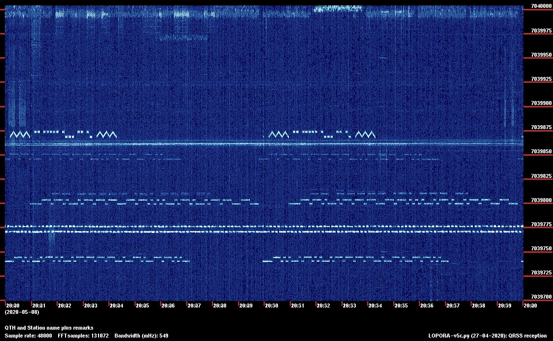
Of course I wanted to be shure that the high audio frequency was possible! A test with a simple direct conversion receiver proved that the high audio frequency was possible. QRSS stations were received, even though the unwanted sideband was also received! See the picture below, WSPR and QRSS stations! And there had to be a different temperature control for the crystal with an NTC resistance as a sensor. This circuit also had to be designed and tested first. The test circuit worked fine (after a few evenings)! No more problems are to be expected! The design of the 80 meter receiver has to be modified a bit and then the construction can begin!

A test with a simple direct conversion receiver proved that the high audio frequency was possible.
QRSS stations were received, even though the unwanted sideband was also received!
The principle of the sideband suppression
So the 7023 kHz crystal comes from a Pixie transceiver, but there are several kits that use the same crystal. The QRSS band of 7039,85 kHz (+/- 150 Hz) is 16850 Hz lower. It must therefore be a direct conversion receiver with an audio-frequency output of 16850 Hz. The unwanted sideband must be suppressed by the phase method. The advantage of that high audio frequency is that the QRSS band of 300 Hz is only 0.9% around that 16850 Hz. And a very simple phase network of only one resistor and one capacitor can be used in the low-frequency path!
As a mixer I wanted to use the 74HC4066, I had good experiences with that, also with the 80 meter QRSS receiver. There were still some of the brand Toshiba here. And we're going to use as many transistors as possible, not ICs, except for that 74HC4066 switch that's used as a mixer. The design is similar to the 80 meter QRSS receiver, with some modifications.

The principle of the sideband suppression
HF amplifier
At the input is the HF attenuator, a 1k ohm potentiometer, with which the sensitivity of the receiver can be optimally adjusted and overload by strong signals can be avoided.
But why is there a series resonance circuit after the attenuator? It is tuned to the receive frequency of 7039,85 kHz and has a low impedance for that frequency only. This is a high impedance for other frequencies. And so you can connect multiple receivers for different frequencies in parallel with the antenna without attenuating each other's signals!
After this series circuit you will see the tuned circuit consisting of the coils of 0,47uH, 4,7uH and trimmer of 130pF. This selective circuit only allows a small band around 7039.85 kHz to pass through and attenuates the unwanted signals at other frequencies. You will not easily find a 130pF trimmer. But the value is composed of a parallel connection of a capacitor and a trimmer of a smaller value. For example, a capacitor of 100pF and a trimmer of 40pF. Or a capacitor of 82pF and a trimmer of 70pF.
Due to the high emitter resistance of 470 ohms, the first transistor has a high input impedance. So it will not dampen the tuned circuit. The capacitor with a small value of 10pF and resistor of 1k ohm protects the transistor somewhat against high voltage peaks and the resistor also prevents oscillation of the HF amplifier. The second transistor has a low-impedance output, which is necessary to drive the phase networks. And both transistors and the tuned selective circuit also amplify the signal.

Schematic diagram, almost all transistors! But it needs some explanation to understand everything!
High-frequency phase networks
After the HF amplifier, the signal is split into two signal paths. A 90 degrees phase difference must be realized with the aid of phase networks. The 48pF trimmers and 470 ohm resistors do this. With the trimmers you can optimally adjust the phase so that the suppression of the unwanted side band is maximized. One phase network is at -45 degrees and the other at +45 degrees, the difference is then 90 degrees. And does one signal need more signal and the other less? Then you adjust one trimmer to -50 degrees and the other to +40 degrees. So the trimmers not only adjust the optimal phase, but also the optimal amplitude!
And if the low frequency phase networks do not differ exactly 90 degrees, you can correct this with the trimmers. Then the phase difference in the high-frequency phase networks is a little less or more than 90 degrees. You do not notice that the reception sensitivity decreases slightly, it is probably not even measurable!

At the end of evening one
Mixers
My QRP sets usually have a 74HC4066 as a receiver mixer. A simple, inexpensive solution that works fine, no audio detection of strong broadcast stations and excellent sensitivity. So it makes sense to use it here, I still have some! But you can also use a better, more modern FST3253 chip.
The mixers are simple semiconductor switches that are switched by the crystal oscillator of 7023 kHz. The IC 74HC4066 contains four of those switches, we only use two. A disadvantage is that HF signals and audio frequent signals are also passed from the input to the output. For example noise on audio frequencies of the HF amplifier. But the high-pass filter immediately after the HF amplifier consisting of a capacitor of 1000 pF and a resistor of 470 ohm only conducts HF signals and blocks these audio frequent signals.
The two-resistor voltage divider of 10k sets the mixer input to half voltage, which is 2.5 volts.
After the mixers you will see low-pass filters, each consisting of two capacitors of 1 nF and a resistor of 470 ohms. This filter only conducts low-frequency signals and blocks HF signals from the HF amplifier. This prevents detection of strong AM broadcast stations in the audio amplifier.

At the end of evening two
Low-frequency phase networks and the adder
After the low-pass filters, the two low-frequency phase networks can be found. These are capacitors of 1000pF and resistors of 10000 ohms. The frequency band used ranges from 16700 Hz to 17000 Hz. This is a very small deviation from the central frequency of 16850 Hz. And that is why we can use these simple networks consisting of only one capacitor and one resistor. One phase network shifts the phase by -45 degrees and the other by +45 degrees, the difference is then 90 degrees. And it does not have to be very accurate, it is not necessary to use very accurate components. If the difference is not exactly 90 degrees, no problem! You can correct this with the trimmers in the high frequency phase networks. You do not even notice that the reception sensitivity decreases slightly!
And it works! The suppression of the unwanted side band (7006,15 kHz) is more than 45dB and even more than 55dB at the central frequency!
The signals from both networks must be added. This is done in the circuit with two transistors and a common 4700 ohm collector resistor. The 1k ohm emitter resistors convert the input voltage into a current and both currents are added into the 4700 ohm resistor and converted back into a voltage. You do not need to use "paired" transistors with identical gain. The circuit also amplifies a bit: 4700 ohms / 1000 ohms or 4.7x.
By means of a switch, a 10nF capacitor can be connected in parallel to the 1nF capacitor. This 1nF capacitor works as a high-pass filter, so that all signals below 10 kHz are attenuated. But if you want to listen to the receiver, you can disable this high-pass filter with the switch.

At the end of evening three
Low-frequency amplifier
And then there are two transistors, the low-frequency amplifier. The first transistor has an emitter resistor of 330 ohms and a collector resistor of 6800 ohms. Due to the 330 ohm emitter resistor, this stage has a high input impedance and a decent negative feedback, so that practically no distortion occurs. The gain is approximately 6800 ohms / 330 ohms = 20x. Not quite true, the gain is only 12x, because the last stage loads the 6800 ohm resistor with 10k ohms.
The last stage also has a lot of negative feedback. At the base is a 10k ohm resistor and between the collector and base a 100k ohm resistor. The gain is 100k / 10k = 10x. The 47k ohm resistor ensures the correct DC setting.
The 1 nF capacitors attenuate the high frequencies. And the 1k resistance at the output ensures that the output stage is at least loaded with that 1k impedance and is also a protection if you connect something crazy to the output.

At the end of evening four
Crystal oscillator
And then another very important part, the crystal oscillator that controls the mixer. First I made a test circuit of the crystal oscillator. The original oscillator design was based on a Clapp oscillator. But the oscillator circuit used here is much more universal and operates over a very wide frequency range without the need to adjust capacitor values. Two transistors form the oscillator and it is followed by an extra stage that turns it into a square wave. You can change the 100k resistance of this last stage if the duty cycle is not 50%. You can measure this by measuring the average voltage on the collector, this must be half the supply voltage of the oscillator, so 2.5 volts.
The frequency of the oscillator does not have to be exactly 7023 kHz. That of my receiver is 7022,783 kHz or 217 Hz lower. The center of the band is at the audio frequency of 17067 Hz instead of 16850 Hz, but that is not a problem.
However, originally the oscillator frequency was too low and the audio band would be above 80% of 44100/2 = 17640 Hz. Therefore, a series capacitor of 18pF is fitted. This must be a good, stable capacitor, I used a styroflex capacitor. A trimmer will probably also be possible.
Crystal oven
The oscillator must be very stable for QRSS reception. A drift of less than 1 Hz per hour is desirable. And also an absolute accuracy of 5 Hz. An ordinary crystal oscillator is not stable enough, there is too much frequency drift due to temperature variations. The crystal is kept at a constant temperature by a "heater" resistor and an NTC resistor as temperature sensor. The two transistors BC547c form a differential amplifier. The output drives the BC557 driver transistor for the "heater" resistor. Select the emitter resistance of the left transistor BC547c so that the circuit does not oscillate and does not show too many oscillations. You can see this by means of the LED. I use a 120 ohm resistor. Just after power-on, oscillations are normal, but they have to damp pretty quickly till a stable situation arises.

The "heater" resistor is soldered and glued directly to the crystal housing.
The NTC resistor must make physical contact with the crystal and also with the "heater" resistor!
Otherwise, the control may become unstable.
The "heater" resistor is soldered and glued directly to the crystal housing, as well as to the NTC resistor. It is very important that the NTC resistor makes good physical contact with the "heater" and also with the crystal. The NTC resistor must be heated up as quickly as possible by the "heater" resistor. As a result, the heating of the crystal will be slow and the circuit will be stable. And everything is glued together by a thick blob of Glue stick glue, which you can melt with your soldering iron. This blob also provides a slowing warm up effect and a calmer control.

A low control resistance of 120 ohms in the crystal oven controller.
Very accurate, but also many oscillations.

A high control resistance of 1000 ohms in the crystal oven controller.
A little less accurate, but still sufficient and much quieter.
Power supply
The 220 ohm resistor, capacitors and 100nF capacitors are decoupling capacitors for the power supply to suppress interference signals.
And then there is a 5 volt supply with a simple transistor. This is the supply voltage for the 74HC4066 and the oscillator. I did not have a suitable zener diode. But on the base is 6 volts, so on the emitter approximately 5 volts. The 100 ohm resistor in the collector is a current limiter, useful when you accidentally make a short circuit...

For the adjustment, the simple GPS frequency standard is used.
Adjustment
For the adjustment, the GPS frequency standard is used. The description can be found on this website. You can set the frequency to any value between 1 Hz and 10 MHz, even a few MHz higher with reduced quality. The low-frequency output is connected to the audio input of the PC and an audio spectrum analyzer program (there are many) is started on that PC. The GPS frequency standard is connected to the antenna input via a high-resistance resistor or a "pick-up" wire. Set the frequency of the GPS frequency standard to the QRSS frequency of 7039,85 kHz. Adjust the input circuit trimmers to maximum. You can vary the level of the test signal with the 1k attenuator potentiometer.

Adjustment of the suppressed sideband. The orange curve is the desired signal at 7039,85 kHz.
The unwanted side band suppression (7005,7 kHz) is more than 45dB
and even more than 55dB in the middle of the band.
Now comes the difficult part, adjusting the sideband suppression, that will take quite some time.
Set the frequency of the GPS frequency to the QRSS frequency of 7039,85 kHz and adjust the signal with the 1k attenuator so that the signal is at the top of the spectrum display. Read the audio frequency. With my receiver that is 17068 Hz. Then set the frequency of the GPS frequency to the unwanted side band, which is 7039,85 kHz - 2x the read audio frequency. So for me 7039,85 kHz - 2 x 17068 = 7005,714 kHz. Now you will see a weaker signal on exactly the same place in the spectrum. Now adjust the two trimmers of the high-frequency phase network so that this signal is minimal. Always turn one trimmer slightly, then adjust the second to minimum signal and repeat it to find the most optimal positions.

Real simple "Barefoot Technology"! A simple loop antenna for the first experiments!
And... how does it work?
The sensitivity is excellent. When connected to a loop antenna, you can hear that the noise decreases enormously when you turn the HF attenuator back. The frequency stability is also excellent. There are no unwanted signals that are often caused by overdriving by strong broadcasting stations with these types of simple receivers.
And the side band suppression of the unwanted side band (7005,7 kHz) is over 45dB and even over 55dB at the center frequency! There are no audible signals from that unwanted sideband. That was the case with my first simple direct conversion receiver without that unwanted side band suppression.
QRSS signals were immediately received with the laptop and loop antenna! But it take be a while before the results will be visible on the Active QRSS Grabber List by Scott Harden. Some USB audio dongles for the Raspberry Pi have to be ordered and not all of them are usable! More about that later!
And... soon the first signals were received!
M0BMN, G0FTD, M0RON, GJ7RWT, S52AS (non-stacked), DL1ENZ

And... N8NJ op 7039,910 kHz!

And... a few rhinos!!!

Bad weather! Thunderstorm and lightning!
QRSS Plus Automatically-Updating Active QRSS Grabber List by Scott Harden
Index PA2OHH