FREQUENCY CALIBRATION OF THE
30 METER QRSS BEACON RECEIVERS
(2011)
KLIK HIER VOOR DE NEDERLANDSE VERSIE
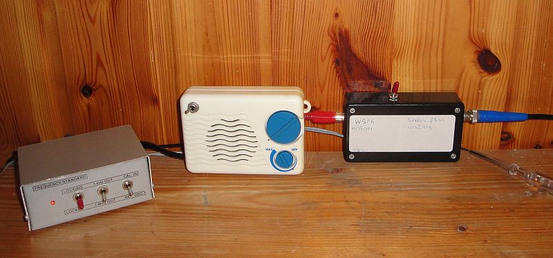
The QRSS beacon reception station with frequency
standard locked at BBC Droitwich on 198 kHz.
Frequency calibration of the 30 meter QRSS beacon receivers
Here in the shack is a frequency standard available, locked at the long wave transmitter BBC Droitwich on 198 kHz. This 1 MHz standard is used as a reference frequency for the frequency counter. But for the calibration of the QRSS beacon receiver, it is not possible to connect a frequency counter to the local oscillator. Connecting the frequency counter to the oscillator does influence the frequency too much. And a calibration with a frequency counter is not simple, the receiver has to be opened and you have to find the right point to connect the probe of the frequency counter. But there is a better method. The advantage of it is that you also calibrate the sound card and even the software with it. And you do not need a frequency counter, just a cheap and quite simple to make frequency standard!

The block diagram of the frequency standard.
We are going to use the 20 kHz square wave signal for the calibration.
Frequency calibration with the frequency standard, but without frequency counter
In the frequency standard, a 20 kHz signal can be taken from one of the dividers. A square wave generates signals on all odd harmonics. And 10140 kHz is the 507e odd harmonic! We connect the 20 kHz signal to the antenna input of the receiver and increase the RF attenuation of the receiver strongly to avoid overloading. At the frequency of 10140 kHz, a line will be visible in the spectrum display.
It can be done even more simple. A short antenna wire of 20 cm connected to the 20 kHz output is sufficient to receive the 507e harmonic of that 20 kHz, that is 10140 kHz, via the antenna of the receiver. Calibration is really simple now, you do not have to disconnect or connect anything. Just switch on the frequency standard during QRSS reception and check if the 10140 kHz calibration signal is not too high or too low in the spectrum display. Examples of what will appear in the spectrum display can be found here below. You can even see that at the beginning of the spectrum display, the control loop of the frequency standard has not been completely stabilized.
Left the spectrum with a coaxial cable between the frequency standard and the QRSS receiver,
right the received spectrum with a short wire connected to the 20 kHz output of the frequency standard.
How to get the 20 kHz signal from the frequency standard
At pin 7 of U3A (QD) is a square wave of 20 kHz. The wire between switch S3 to pin 7 of U2A (QD) is rerouted to pin 7 of U3A (QD). Now we do have a 20 kHz signal in the 1 MHz position of S3 instead of a 1 MHz signal. That 1 MHz signal was not necessary anymore, it was used for the frequency counter with nixie display tubes and that was donated to charity.

Diagram of the frequency standard
big diagram
Detailed description of the frequency standard
Frequency standard modified for the French long wave transmitter Allouis on 162 kHz
This transmitter is also controlled by a frequency standard. With some modifications in the dividers, this circuit can easily be made suitable for it. The 20 kHz signal can be found after the by 8 divider of the by 80 divider.
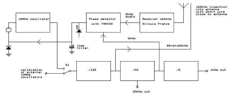
Block diagram of the frequency standard for the French long wave transmitter Allouis on 162 kHz.
Detailed description of the frequency standard for Allouis
BACK TO INDEX PA2OHH

