LOW VOLTAGE TUBE RADIO
(2019)
KLIK HIER VOOR DE NEDERLANDSE VERSIE

Nostalgia! Circuits with tubes! Very different from today's electronics!
Simple radio with tubes
Tubes! A new idea for a "Barefoot Technology" project! A simple radio with tubes, completely without semiconductors. And according to the "Barefoot Technology" rules, simple, minimalistic and safe! A simple radio with tubes, that is not so easy... High voltages and a dangerous mains voltage, that is not "Barefoot Technology". Alex once noticed that these high voltages are dangerous. When he put his head into a tube radio to hear where that hissing came from, the high-voltage capacitor exploded. He didn't touch a radio for a week...
I thought about battery power, 15 batteries of 9 volts in series for a minimum anode voltage of 135 volts and 4 of 1.5 volts for the 6.3 volt glow voltage. Quite a simplification! No dangerous mains voltage, no large transformer, no rectifier tube. But no, those 19 batteries, that was not what I wanted.
It had to be a simple medium wave radio with a ferrite antenna.
With such a nostalgic tube, but without dangerous high voltage!
Barefoot technology, that's the solution!
Suddenly I knew it! "Barefoot Technology", less instead of more, that's the solution! A much lower voltage for the tube, then you have no dangerous high voltage, no dangerous mains voltage and no large power transformer and no rectifier tube! A real "Barefoot Technology" Radio with tubes! If you connect the two 6.3-volt filaments of a double triode in series, you can supply them with 12-volt and that is also the low anode voltage. A car battery or a normal 12 volt power supply!
Can an old fashioned radio tube already work with a low voltage? Just try and... yes, it is possible! It is possible to make a simple radio with a tube that works on a low voltage! No dangerous high voltage and no high voltage components! But nostalgia and a nice experiment! With a double triode, two triodes in one housing. An ECC81, ECC82, ECC83 or ECC88. Not a special tube for battery power, but a real old-fashioned tube with indirectly heated cathode!
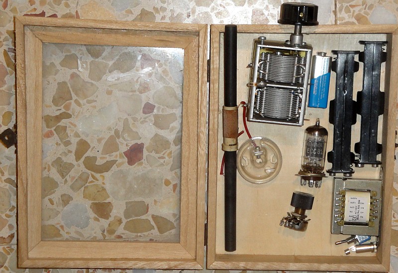
It had to be a simple medium wave radio with a ferrite antenna. No weak signals, because at such a low voltage a tube does not work optimally. I bought a wooden box with a transparent lid as a housing so you can watch the tube glow! I received beautiful parts from a sponsor. Tubes, a nice tuning capacitor, a beautiful tuning unit and a ferrite antenna.
First some drawings!
Which tube?
First some drawings.
Which tube? A stupid question! The one with the highest gain of course! Fortunately, we have the internet, because Merlin Blencowe had done extensive research and came to a completely different conclusion! At a low anode voltage, the electrons are pulled to the anode much less effectively. And we can only apply a small negative grid bias. That causes a decent grid current and a low input impedance of a tube! High gain is not the most important factor. We must choose a tube that has a low grid current at low anode voltages! And that is an ECC82.
Download the complete article by Merlin Blencowe: Triodes at Low Voltages by Merlin Blencowe
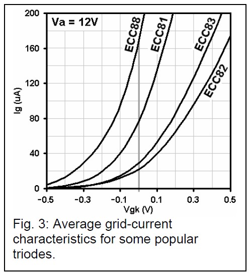
The grid current graph from Merlin Blencowe's paper. An ECC82 does not have the most gain,
but the least grid current with a low anode voltage. And that is more important than much gain!
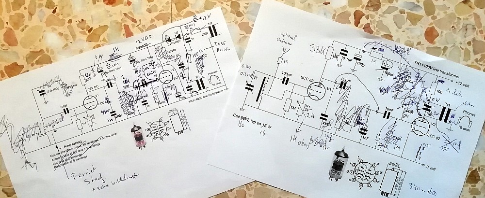
The diagram
V1 is the detector tube and forms a Hartley oscillator with the coil on the ferrite antenna. When this is set to the edge of generation with the 2k potentiometer, the gain and therefore the sensitivity is maximum. The tube has no cathode resistance and therefore no negative grid voltage. The cathode-grid transition therefore works as a diode or amplitude modulation detector. An anode resistance of 33k proved to be the best, you can experiment with it. The 1nF capacitor between anode and ground suppresses the high frequency from the first tube to the second tube. The power supply is additionally filtered by the 100uF and 0.1uF capacitors and 1k resistor. In the original design, the antenna connection was not fitted. The sound was not really loud. But the receiver worked much better with an antenna of 5 to 10 meters in length. The volume control has therefore been replaced by the antenna connection, the volume can also be adjusted with the feedback, the 2k potentiometer. After all, this allows you to set the sensitivity.

The finald diagram. The original schedule has changed quite a bit!
V2 is the low-frequency amplifier stage. The output is connected to headphones via an audio transformer. This is a 10 watt - 100 volt audio transformer used in audio systems for offices and buildings. They are available everywhere in various variants. The headphones are connected to the 16 ohm output. For the anode connection, choose the connection that gives the best result. The 100 ohm resistor is fitted as a fuse and measuring resistor to measure the anode current. The anode current in milli amps is 10x the voltage across the resistor. And if something is wrong in the circuit, the current through the transformer is limited.
Normally such a tube has a cathode resistance for the negative grid voltage. But you will not find it here. With such a low anode voltage, you only need very little negative grid voltage. And that is caused by the grid current across the 1M ohm resistor. A resistance of 1M ohm was the best. I also did some experiments with a positive grid voltage, but that gave a worse result. The negative grid voltage caused by the grid current is about -0.6 volts. Far too little for a high anode voltage, but fine at 12 volts.
The anode current is only very small, about 0.25-0.3 mA, but this is sufficient and will certainly not set the transformer into saturation! Funny, 140 mA glow current for less than 1 mA total anode current! A small electric heater!
Construction has started. Here still with the later removed volume control.
The construction
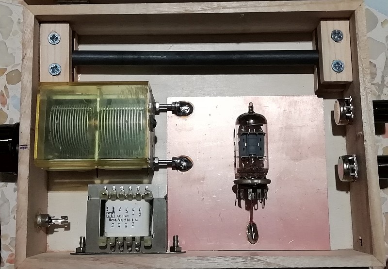
A wooden box with transparent lid. Then you can see the tube glowing and also see the beautiful antique tuning capacitor and transformer. That gives that real nostalgic feeling. A piece of circuit board is glued to the bottom with neoprene glue (contact glue). A tab of the tube holder is bent and soldered to the circuit board. And the center pin of that tube holder is supported with a thick copper wire. A little tinkering with wood, glue and screws, just see how you can do it.
Here I was still optimistic and I mounted a volume control. But soon it was replaced by an antenna plug to improve the reception.
The 80 turns on the ferrite rod with the branch on 16 turns.
But 60 turns with a tap on 12 turns would have been better.
The ferrite rod antenna
The litz wire of the coil was slightly damaged, so unusable. Because when only one strand of the winding is interrupted, the quality of the winding is very poor! So a new winding was made from red mounting wire. The quality is worse than a perfect winding of litz wire...
The ferrite rod was just a little too long. But with the angle grinder, that problem was solved in a few seconds.
I thought that 80 turns with a tap on 1/5 or 16 turns was fine. But the 1605kHz highest frequency of the medium wave was just not reached. So 60 turns with a tap on 1/5 or 12 turns would have been better. The range is 340 - 1600 kHz, so I can receive the amateur band 472 - 479 kHz (635 meters). Only telegraph signals are allowed there. But I don't expect to ever receive anything there with this nostalgic low voltage tube radio.
Just normal mounting wire and a little glue, while drying the glue, clamp everything with pegs and it works!
The audio transformer. Choose the connection that gives the best result

Ready!
And how does it work?
It works! Many evenings I listened to all those medium wave stations. I'm probably the only listener, or do you know someone who listens to the medium wave? Only 12 volts and still a great reception! The feedback works perfectly, very smoothly! It is best to set the feedback so that the receiver just oscillates. When a station is received, that oscillation stops, or synchronizes, and reception is perfect.
But the sound with only the ferrite antenna was a bit soft. Only a few strong stations were received. With a 5-10 meter long wire antenna, the sound strength was much better and many medium wave stations were received in the evening. But a volume control is not necessary! Optionally, you can use the feedback to decrease the volume. The 12 volt supply voltage makes the receiver safe and simple. But such a receiver works better at with higher anode voltage.
And indeed, the ECC82 did it much better than the ECC81!
Many evenings listening to all those medium wave stations! Just like Alex barefoot on the
ice cold stone floor. I learned simple thinking and living from him during my student days!
Index PA2OHH