UNIVERSAL VFO-BFO MODULE WITH SI5351
(2020)
KLIK HIER VOOR DE NEDERLANDSE VERSIE
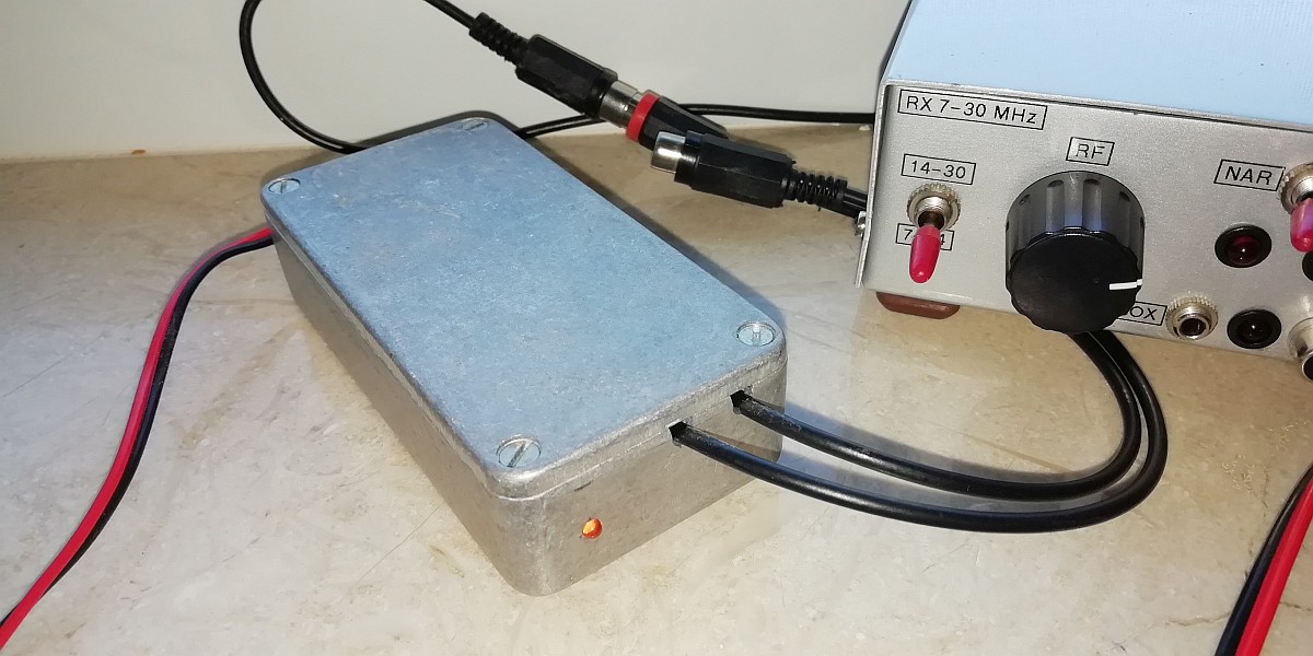
The universal VFO-BFO module. Here connected to a direct conversion receiver.
Only the VFO output is used for this simple receiver.
Universal VFO-BFO module
Such an SI5351 generator module that you can order via the internet, I must be able to do something with that! It has 3 generator signal outputs, so I can replace a VFO and a BFO with it! And control it with the famous Arduino Nano! A universal VFO-BFO module, that's the idea. It can be used with simple direct conversion receivers. Then you only use the VFO output signal. With a simple "Barefoot Technology" direct conversion receiver you can receive almost as much as with an expensive commercial radio. But for digital modes you have to use a DDS or this universal VFO-BFO module for sufficient frequency stability! But the universal VFO-BFO module can also be used with super heterodyne receivers with an intermediate frequency and crystal filters. Then you use not only the VFO signal, but also the BFO signal.
The big challenge is of course how to control that SI5351 with the Arduino Nano. Silicon Labs has a document AN619, 63 pages, and I have to read that first. Well, at first I didn't understand it at all! Fractional Multisynth dividers and a strange number 1,048,575... There are 8 clock signals, but my 10 pin module has only three. However, the other 5 are in the chip and must be "powered down" to save energy.
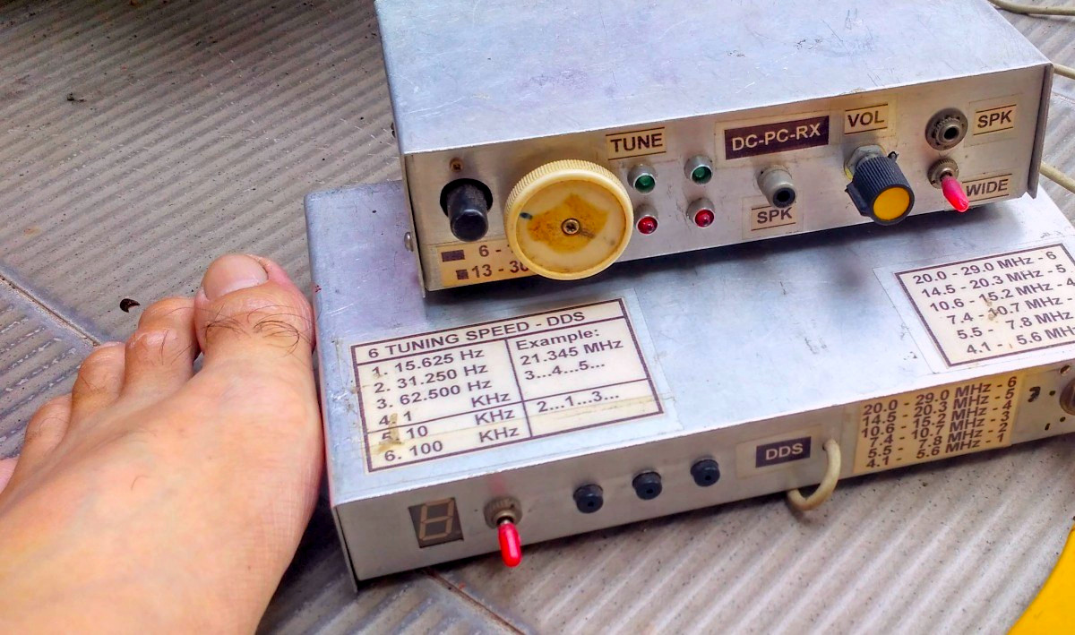
With a simple "Barefoot Technology" direct conversion receiver you can receive almost
as much as with an expensive commercial radio. But for digital modes you need
a DDS or the universal VFO-BFO module for sufficient frequency stability!
Only two of the three outputs are usable
There are two PLL circuits, PLLA and PLLB. The frequency of these PLL's have to be set. The second Multi synth stages must be set to an even integer value for low jitter. So only two of the three outputs can be used simultaneously! Step by step everything becomes clear. It is a challenge to understand everything in the document AN619. Fortunately, there are 8 clock signals so that is more or less 8x the same story. I have to read that only once.
I found a few examples on the internet. One with the SI5351 library, but it used PLLA for both outputs and no integer value for the second Multi synth stages. I would have to modify the entire library and that is too difficult. But the simpler program of OE1CGS (Christophe) Arduino sketch was usable and could be modified. No library or extra files, very clear and logical. This simplicity fits perfectly with the "Barefoot Technology" philosophy! Simple and easy!
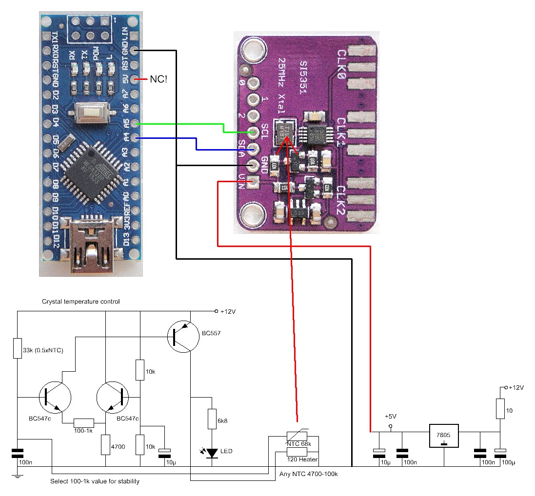
The schematic diagram and wiring between the Arduino Nano and the SI5351 module.
The hardware
My idea was to use the universal VFO-BFO module for QRSS reception. Then the frequency stability is very important. That is why a crystal oven has been added. It works with an NTC resistor as a temperature sensor and a 120 ohm resistor as a heating element. These are glued to the crystal of the SI5351 module.
The two transistors BC547 are a differential amplifier, the BC557 controls the "heater" resistor. You can choose the value of the resistor 100-1k yourself. I use 150 ohms. A low resistance gives a high accuracy, a high resistance a calmer control.
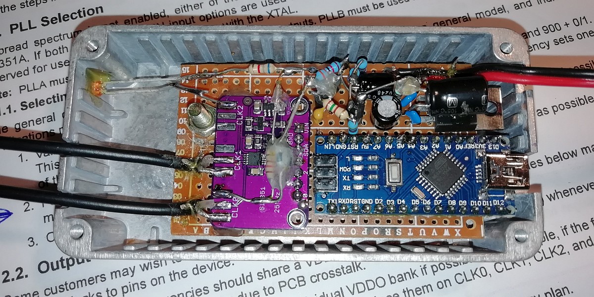
Inside view
No radio interference please!
The prevention of radio interference is very important for the reception of weak QRSS signals. I had a simple solution for that. The SI5351 module has its own 5 volt power supply. The Arduino Nano is powered via the USB connector by the PC, not from the same 5 volt power supply of the SI5351 module. When the frequency of the SI5351 module is programmed by the Arduino Nano, it is disconnected from the USB cable. It no longer has a supply voltage, is now switched off and cannot cause radio interference.
But if you want to use the module as VFO and BFO for a normal receiver, the crystal oven and 5 volt power supply for the SI5351 are not necessary. Then simply connect the SI5351 module to the 5 volt of the Arduino Nano. The Arduino is connected to your PC via the USB cable and you can tune the module with the program running on the PC.
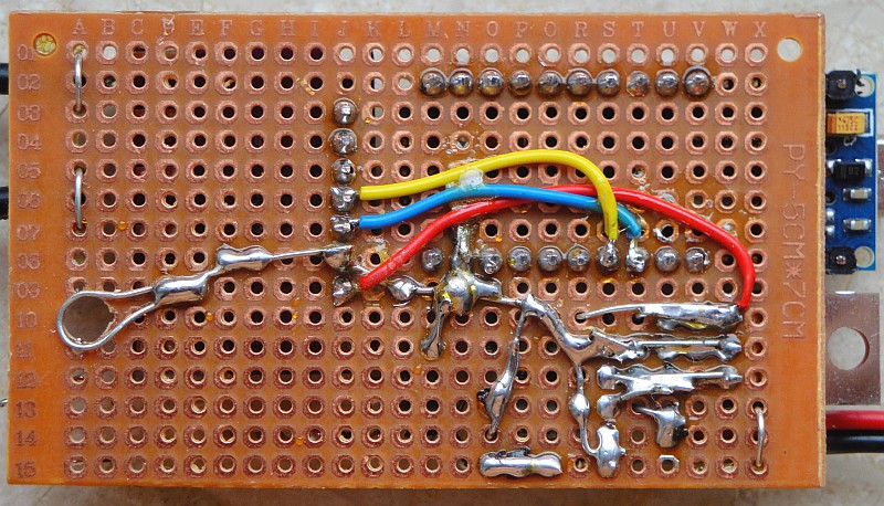
Bottom
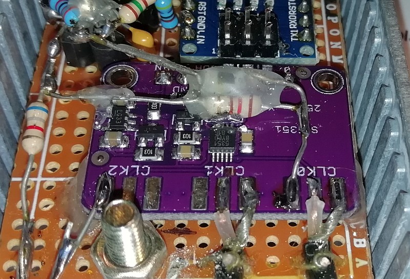
The heater resistor is glued to the crystal together with the NTC resistor.
You can do that with a glue stick, which you can melt with your soldering iron.
Installation of the software
Create a new directory and copy the files in the following ZIP file to that directory:
Software for the Arduino Nano
In the directory VFO-BFO01 you will find the program "VFO-BFO01.ino" that you have to upload in the Arduino Nano. The program is based on the OE1CGS (Christophe) Arduino sketch. Christophe has figured out how to program the SI5351 module for the CLK0 output. The program was easily adaptable for two CLK outputs (CLK0 = VFO, CLK1 = BFO). And a serial RS232 routine has been added, so you can set the frequency via the USB port.
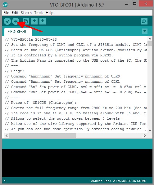
Programming the Arduino Nano. Load the program "VFO-BFO01.ino"
and press the arrow symbol just below "edit" to upload it.
Programming a micro controller has never been so easy, even a layman can learn it in a few minutes! You can find it at https://www.arduino.cc/ under downloads. And there is much more information about the various Arduino versions. I use the Arduino Nano.
Download and install the IDE. Connect the Arduino Nano with your USB port on your laptop or PC and with "Tools - Port" you can select the correct COM port. When it works, you have the correct COM port.
With "File - Open..." you can open a program, that is a file with the extension ".ino". With the first V on the toolbar, you can check if a program has errors. With the second round with an arrow you can compile the program, upload it and then you are ready!
A program consists of two parts. The "void setup()" part contains the configuration, for example which ports are configured as input or output. The second part "void loop()" contains the program. More information can be found on the above mentioned website of Arduino.
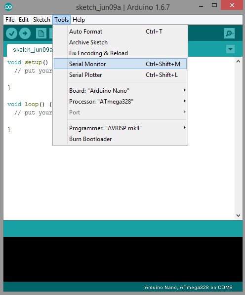
Starting the Serial Monitor in the Arduino development environment
Programming the frequency
For this you have to start the Serial Monitor in the Arduino development environment.
You can now simply use the following commands to program the SI5351! Give it a try, when you send a question mark, you will get the software version back as information.
===
Usage:
Command "?" print information about software version
Command "Annnnnnnn" Set frequency nnnnnnnn of CLK0
Command "Bnnnnnnnn" Set frequency nnnnnnnn of CLK1
Command "An" Set power of CLK0, n=0 = off; n=1 = -8 dBm; n=2 = -3 dBm; n=3 = 0 dBm
Command "Bn" Set power of CLK1, n=0 = off; n=1 = -8 dBm; n=2 = -3 dBm; n=3 = 0 dBm
===
Programming the frequency using a special program
But this is of course not practical for tuning a receiver. You can set a frequency only once in this way. For operating a radio receiver there is a program written in Python. This is the program "VFO-BFO01-v01a.py" which you can also find in the ZIP file.
Before using this program you need to install Python. This is very simple. But first read something about Python by clicking on the following link:
WHAT IS PYTHON AND HOW TO INSTALL PYTHON
Because the Python source code is written in ASCII, you can easily adapt the program to your own wishes. Consider, for example, the size of the screen, the colors, etc.
Open Python 3 (IDLE) and open "VFO-BFO01-v01a.py"
Then choose "Run Module". Then you first get a question about which RS232 port to use.
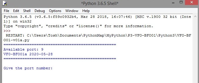
It is clear which port to choose!
And you will see the following GUI to control everything.
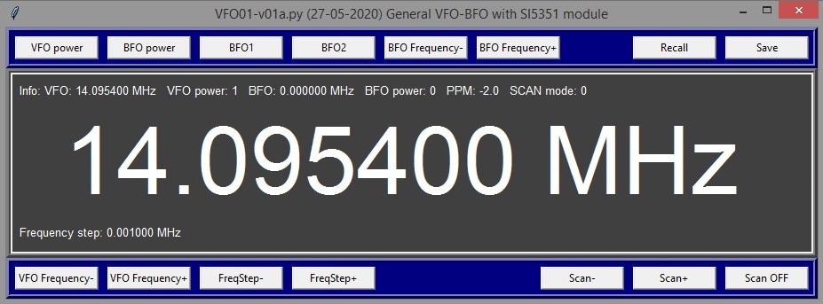
The Graphical User Interface with which you can control the VFO-BFO module.
The VFO-BFO module is connected to your PC with a USB cable.
VFO power & BFO power
To set the power: n = 0 = off; n = 1 = -8 dBm; n = 2 = -3 dBm; n = 3 = 0 dBm.
CLK0 is the VFO output, CLK1 is the BFO output.
BFO1 & BFO2
This allows you to choose two BFO frequencies, for example for LSB and USB reception. You have to put these frequencies in a configuration file.
BFO frequency- & BFO frequency +
The BFO frequency is increased or decreased by the Frequency step value.
Recall & Save
For loading and saving a configuration file. You can edit this file with an ASCII text editor. In a configuration file you can also set the frequency correction in PPM.
VFO frequency- & VFO frequency+
The tuning. When pressed, the frequency is changed by the value of the Frequency step.
FreqStep- & FreqStep+
Set the frequency step size of the tuning and also of the scan.
Scan- & Scan+ & Scan OFF
For the scanning of a frequency band. The VFO frequency is continuously changed with the value of the Frequency step.
First results
The universal VFO-BFO module was connected to a simple direct conversion receiver, nothing special. And ... signals were soon received! The SI5351 module with temperature stabilized crystal is stable.
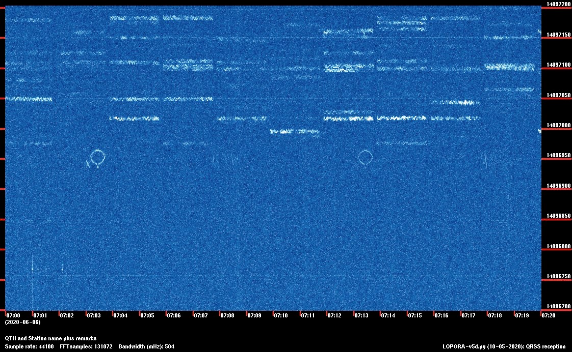
A balloon at 20 meters
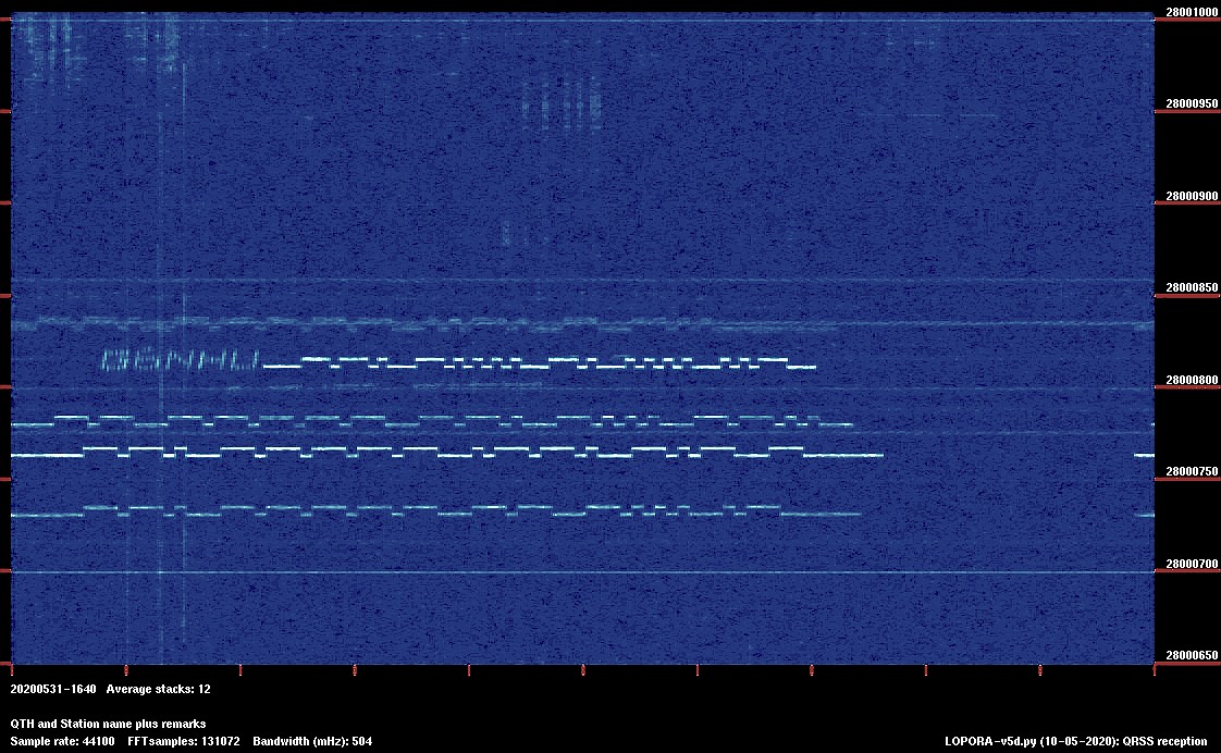
5 signals at 10 meters
Index PA2OHH


