HiperVXO
This is part of the brazilian famous 40m DSB transceiver "GIGANTINHO" (small giant). Jair PY5BE and others hams had builded about 18 radios like that.
Looking mainly frequency stability and the range covered of VXO that took Celso PY2XT to phone Jair... and Jair send the schematics via fax.
This circuit is similar to "super vxo" who was developed by Japaneses who had been the first ones to test this type of oscillator.
We find in the WEB many circuits that use the same technique of super vxo, and until it had competitions competitions to know the maximum reached frequency range.
We are looking a form to duplicate using easy parts to find.
The circuit

"GIGANTINHO" VXO
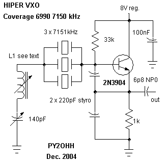
The VXO of the "Gigantinho" has its major secret in the inductor (IFT coil) the Jair uses a IFT coil miniature 10mm 455kHz with the capacitor removed, according to Jair, it can be necessary the removal of some turns so that the VXO will cover the band completely.
The capacitor between emitter and base is styroflex and between emitter and the ground is NP0. One has compensation of temperature opposes of the other, this aids to hold the VXO frequency.
The Inductor of emitter is made on the body of an resistor of 100k 1/8W with 120 turns overlapped of wire AWG # 40.
Our experiments
We use the following circuit

3rd assembly experimental VXO
1st Assembly:
We use two capacitors of 820pF styroflex, a commercial coil of 12ÁH in the place of the 1K resistor and ajustable coil of 80 turns of wire AWH #40 in a 7mm OD form in the place of the IFT coil.
The oscillator was built in UGLY style with square shaped islands, cutted with a hand saw.
The oscillator was open over the experiment table.
The Frequencymeter used has 10Hz of resolution.

1st assembly graphics
Although the VXO still opened overthe table it keept like a rock very stable, after 12 minutes of heating.
We built this circuit in a box with a tuned buffer for 40m, I made a doubler with tuned buffer for 20m and a tripler with tuned buffer for 15m.
I am using this hiperVXO in 40m DSB (with MARITACA project look in other place in my home page) ... in more than one hour QSO without touching in the frequency knob ....
2nd Assembly
We place a commercial inductor of 39ÁH who looks like a 1/4W resistor of in the place of the adjustable inductor.
We kept the same measurement conditions.

2nd assembly graphics
The circuit was not stabilized in a reasonable time.
We replace the capacitors for 120pF plate and got practically the same resultad.
3rd Assembly
We mount as the schematics.
We made the inductor with 100 turns of wire 0,15mm OD in a bakelite form with 7mm OD with two soft ferrite cores type thread, we internally fix with an elastic wire about #1mm OD (used by dressmaker and it is fabric covered).
As the VXO did not linearity with a step in 7100kHz jumping to 6200kHz we substitute the original emitter inductor for a 1K 1/4 W resistor.
That resulted in good linearity.
We adjust to the inductor until the minimum frequency of 7000kHz are reached.
We kept the same measurement conditions.

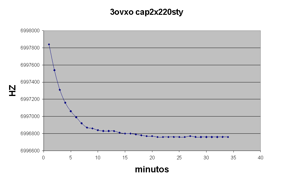
The result was excellent, despite the stability delaying to happen.
Conclusion of steady tests
We will make new tests (and pictures) with hiperVXO in other frequencies and will bring the results here.
(P.S. We made a hipervxo using 3 3579khz xtals, it reaches 3200khz like a rock and reaches 3000khz with a drift of about 150Hz per hour, I use two adjustable coils and the same circuit ...my friend Lobato PY4JR also made this hiperVXO with same results)
73 from PY2OHH Miguel
HiperVXO
Este é parte de um projeto famoso "GIGANTINHO" que povoa a faixa dos 40m, o Jair PY5BE com outros amigos construíram 18 rádios como este.
Foi devido a principalmente a estabilidade de freqüência e a cobertura do VXO que levou o PY2XT o Celso a telefonar para o Jair... O Jair passou o esquema via fax ....
O circuito é muito semelhante ao "super vxo" difundido pelos colegas japoneses, que foram os primeiros a testar este tipo de oscilador.
Encontramos na WEB muitas referencias a circuitos que utilizam a técnica do super vxo, e até houve concursos para se saber do alcance possível.
A diferença entre o circuito do PY5BE Jair e dos outros colegas e a praticidade e procuramos uma forma de reproduzi-lo utilizando componentes facilmente encontrados no nosso comercio.
O circuito

O VXO do Gigantinho tem seu maior segredo no indutor (IFT coil) o Jair utiliza uma bobina de FI miniatura de 455kHz com o capacitor removido, segundo o Jair pode ser necessária a remoção de algumas espiras para que o VXO cubra a faixa completamente.
O capacitor entre emissor e base é styroflex e o entre emissor e terra é NP0. Como um tem compensação de temperatura contraria a do outro isto ajuda a segurar o VXO.
O Indutor de emissor é enrolado sobre um resistor de 100k 1/8W com 120 espiras sobrepostas de fio AWG #40.
Nossas experiências
Utilizamos o seguinte circuito

3o VXO experimental
1a Montagem :
Utilizamos dois capacitores de 820pF styroflex, uma bobina de12ÁH comercial no lugar do resistor de 1K e um indutor ajustavel de 80 espiras de fio 40.
Controlamos o oscilador que foi montado no estilo UGLY com ilhas quadradas. O oscilador aberto ficou sobre a bancada. O frequencímetro utilizado tinha a resolução de 10Hz.

Gráfico obtido
Mesmo aberto sobre a bancada o VXO se manteve firme dentro de 30Hz após o aquecimento de 12 minutos.
Montamos este circuito em uma caixa ....
2a Montagem
Colocamos um indutor comercial de 39ÁH tipo resistor de 1/4W no lugar do indutor variável.
Mantivemos a s mesmas condições de medição.

Gráfico obtido da 2a montagem
O circuito não se estabilizou em um tempo razoável.
Substituímos os capacitores por plate de 120pF e obtivemos praticamente os mesmos resultados.
3a Montagem
Montamos conforme esquema.
Enrolamos o indutor com 100 espiras de fio 0,15mm em uma forma de baquelite de 7mm de diâmetro com dois núcleos de ferrite mole tipo rosca, fixamos internamente com um fio elástico tipo de costureira envolto em tecido.
Como o VXO não apresentava linearidade com um degrau em 7100kHz pulando para 6200kHz substituímos o indutor original do emissor por um resistor de 1K 1/4 W. que resultou em boa linearidade e ajustamos o núcleo monitorando a freqüência mínima de 7000kHz.
Mantivemos as mesmas condições de testes.

O resultado foi excelente, apesar da estabilidade demorar para acontecer.
Conclusão dos testes
Faremos novos testes com o hiperVXO em outras freqüências e traremos aqui os resultados e fotos.
(montamos um hiperVXO com 3 xtais de 3579kHz chegamos até 3200kHz como uma rocha e 3000kHz com uma variação media de 150Hz por hora, utilizamos dois indutores ajustáveis em serie conforme descrito... o Lobato PY4JR também montou com resultados semelhantes)
73 de PY2OHH Miguel