2m J-pole antenna using standard European copper pipe Version 4, 16 July 2020 IntroductionThere is an excellent article by N6JSX on e-ham.net with numerous comments, https://www.eham.net/article/2418, which shows how to build a very simple and apparently effective J-pole antenna out of copper pipe. Being an American article it is obviously based on standard copper pipe available in the U.S.A.; I set out to build a similar antenna using metric hardware which is available in Europe. Components necessaryFigure 1 shows the list of necessary parts. With the exception of the N-type connector, all components should be available in hardware shops. Should things get tough, a plumber's merchant should be able to help! I used 22mm outer diameter standard-duty copper pipe, which is common here in Greece. | |
I settled on an N-type connector instead of the more usual SO-239 both because of its PTFE dielectric which doesn't melt while soldering, and due to the better weatherproofing its male counterpart provides.
A thick copper wire (preferably enameled single-strand, from an old transformer or some such) is used to connect the centre pin of the N-type connector to the antenna matching section. This should normally be 3mm in diameter (see Appendix). I used 2.3mm diameter wire which I had lying around; I don't really know how critical the diameter of this wire is.
Figure 1: Components required. | Figure 2: Detail drawing A: Main section T-junction modification. Figure 3: Connecting filed-down copper wire to the N-type receptacle centre pin. |
Construction
Construction was based on the "Alternate feed method for copper pipe J" section of the e-ham article. This has the advantage that the input connector is on the bottom of the matching section, which means that it is possible to have a single-piece main section; this is good for mechanical rigidity.
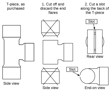
The matching section "L" joins the main section using a T-junction. This T-junction can slide up and down the main section, aiding tuning. The problem is that most (if not all) T-junctions on the market have a necked-down centre part, with flares on either end. This is presumably done because plumbers do not want the T-junction to go up and down the pipe - they want to get water through the T-junction, not RF energy! To make the T-junction capable of sliding up and down the main section pipe, its end flares need to be cut off and a slot needs to be cut along the back of the remaining necked-down centre; see figure 2.
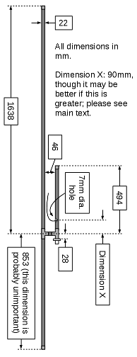
Figure 4 shows the dimensions of the assembly. A 7mm diameter hole is drilled in the matching section pipe, through which the copper wire from the N-type connector exits. This hole was drilled 90mm above the centre of the matching section's T-junction ("Dimension X" in figure 4). However, as will be described later, I think this hole should have been drilled a lot higher; I think that "Dimension X" should be 140mm.
Figure 3 shows a way of connecting the feed wire to the centre pin of the N-type connector. To get a better solder join, a flat was filed into the side of the wire.
Figure 4: Initial dimensions. | Figure 5: Soldering and clamps prior to tuning |
According to Wikipedia's article on J-poles, https://en.wikipedia.org/wiki/J-pole_antenna (which in turn cites John Huggins' superb articles on the subject), the J-pole should not be bolted onto a metal mast. I have used some old wooden planks to hold it up, as can be seen in the main picture. If you do want to support the antenna onto a metal mast, I suppose you could insulate it from the mast by sheathing the lower part of the main section copper pipe (below the T-junction) with a hosepipe or PVC tubing. A balun is also needed in principle, but I didn't actually bother. Tut, tut...
And now to the subject of lightning: This antenna is a wonderful conductor, returning to ground through your cherished transceiver. Make sure you take adequate precautions against lightning, such as properly grounding the coaxial cable where it enters your house. This will be especially necessary if, as suggested in the paragraph above, the antenna is not electrically connected to a grounded mast.
Adjustment
Adjustment was made for lowest VSWR across the 144-146MHz range. There are four parameters to play with (see figures 5 and 6):
1. The position of the T-junction on the main pipe section. Initially, support this T-junction onto the main pipe section with clamps, to allow it to move up and down the pipe when the clamps are loose.
2. The position where the feed wire contacts the main pipe section. A clamp can initially be used to connect this wire to the main pipe section, allowing the point of contact to be moved up and down.
3. The length of the feed wire. It is recommended to initially make this wire 500mm long (total length); this can then be trimmed down to the optimal length.
4. The length of the matching section pipe. This is very critical indeed; I found meanigful adjustment could be made simply by moving the pipe end cap up and down by a few mm!
Figure 6: Tuning | Figure 7: Soldering etc. after tuning. |
Tuning is an iterative process, I suppose you could start with the dimensions shown and then start adjusting everything until VSWR is flat across the frequency range. I found no surprises; I adjusted the main section T-junction position first, then I adjusted the position where the feed wire contacted the main section pipe, then adjusted the wire length (shortest worked best for me). Finally, I moved the end cap on the top of the matching section up and down a little, until I got the best match. After everything was set, the clamps were removed and everything was soldered up as shown in figure 7. The hole in the matching section pipe was sealed with two-part epoxy adhesive. The problem I got is that for best match the feed wire ended up going upwards at a 45 degree angle; see figure 8. This is not good, because raindrops landing on the feed wire will go straight down to the hole in the matching section pipe. Sure enough, this is sealed with epoxy, but it is generally considered good practice to avoid having water dribbling onto seals. What would have been a lot better would be if the feed wire did a "U-bend" downwards, before entering the hole in the matching section. If the hole in the matching section were drilled higher up, for example if "Dimension X" in figure 4 were made 140mm, it should have been possible to make the desired "U-bend". | Figure 8: Detail picture: Feed wire after tuning. |
Finally, the antenna was spray-painted grey, which makes it less obvious to the neighbours!
Conclusion
The antenna only took me a Saturday morning to put together and tune. It works remarkably well, giving great range and unmeasurably low VSWR (<1.1:1) from 144 to 146MHz. However,
A. This antenna is supposed to also work on 70cm. I haven't got a rig to try it with, so I have no idea what it does!
B. I am not too happy with the upward-sloping feed wire, as it brings water down to the sealed hole in the matching section pipe. I think it would be a lot better if the hole were drilled higher, with "Dimension X" in figure 4 made (for example) 140mm.
Should anyone try this antenna and have answers to A. and B. above, I would be very happy if they would let us all know by adding a comment to the original e-ham.net article, getting in touch via QRZ.com or, indeed, on the air...
Thanks to N6JSX and company for a very useful and super-simple-to-build antenna. Also to my dear friend and mentor SV1BY for the loan of the VSWR meter!
Paul, SV1UI
Appendix
Scaling the original e-ham.net antenna:
So-called 1/2" copper tubing actually has an O.D. (Outer Diameter) of 0.625" (15,8mm). "K" type (thick-walled) has an I.D. (Inner Diameter) of 0.527" (13,4mm).
12AWG wire has an O.D. of 2.05mm so with 1/2" "K" type tube, the ratio of diameters between the centre conductor and outer conductor is 13.4mm/2.05mm=6.52. The impedance of the coax "cable" thus formed is Z=138 x [log (Dd/Dc)] / sqrt(er) = 138 x [log(6.52)] / sqrt(1) = 112 Ohms. So this length is a form of matching network, not 50 Ohms!
The European 22mm copper pipe (0.8mm wall) has an I.D. of 20.4mm. This implies that to give the desired 112 Ohm impedance, the centre conductor of the coaxial line must be 20.4mm/6.52=3.12mm.
However, the thickest enamelled wire I had is 2.3mm dia, so that's what I used...