Pre-Ampilfier
I have an old VHF tranceiver and its a little-bit "deaf"!
With the following VHF preamp, I have no problem now to receive any weak signal. Additionally, it has a band-pass input filter which rejects any undesirable signal outside of 2 m. Band.
I have worked manytimes MIR Space Station with this circuit as antenna
preamp and a simple 4 Elements HomeBrew VHF Yagi, always with excellent results.
(clik here for QSL)
There is nothing unusual about this VHF pre-amplifier design.
I was just remindful with PCB of this circuit and the components that
I have used (see SMD ).
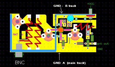
FIG. 1 shows the electronic circuit and FIG.2 the components layout.
 |
 |
The "blue line" on FIG.2 its a sield of tin-can material between input-output . Except the isolation it is necessary in order to be able to conduct the two opposite "ground - tracks" on PCB ( GND A - main ground track and GND-B track)
You must be careful with shield and T1-Gate PCB track ! The shield is a few millimeters above T1-Gate "PCB-track" without solder in this point
( see FIG.3 for details)
On my preamp I've soldered with the same tin-can material every side of PCB. This way we can made an RF-proof box by using as base the PCB of the Vhf pre-amplifier. The PCB is "single-side".
 |
  Top-view of BF982 |
FIG.4 shows the PCB and the BF982 view .
This type of VHF Pre-amp has a maximum gain of about 20 Db or more (depend on T1).
My circuit has a gain of about 15 db with input filter and output attenuator, but its very "quiet" with excellent "noise figure", providing a very clean signal. I think that its more important from a high amplification pre-amp.
The resistors R4-R5-R6 built-in a "PI" attenuation network in the circuit output ( loss about 1 DB). I have used this network for stabillity and good "50 Ohms" termination with the next stage, but on the other hand this network increasing the noise by the same value of attenuation. Actually, if you are sure about the stability of the next stage and looking for the maximum of amplification with the best noise-figure, just remove the 3 resistors and take the output directly from C3 capacitor (not recommended). On the other hand, if you want greater attenuation (1 - 6 Db), the table below giving the values for R4, 5 & R6 in Ohms.
Part List
T1 = BF982
CT = trimer 3-30 pF
R1 = 82 K / 0.25 W
R2 = 33 K / 0.25 W
R3 = 100 Ohm / 0.25 w
R4, R6 & R5 = see Table below
R7 = 100 Ohm / 0.25 W
C1 - C2 - C4 = 1nF SMD
C3 - C6 = 1nF / 63 V ceramic
C5 = 10 uF / 16 V
C7 = 1nF (Feedthrough capacitor)
L1 = 5 turns, 1mm wire, length= 11 mm,
TAP. 1 turn from GND, internal diam. = 6.3 mm
L2 = like L1 without TAP
L3 = 5 turns, 1 mm wire, length 9 mm,
TAP. 1 turn from VCC, internal diam.= 6.3 mm
"Pi" Attenuation Natwork Values
| ATT. | R4 & R6 | ||
| 1 dB | |||
| 3 DB | |||
| 6 DB |
All resistors in OHMS / 0,25 W
Good Luck de Makis SV1BSX (October 1995)
Back to Homebrew-Page