| |
|


|
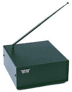
Modifying the Ten-Tec RX-320 Receiver for LF/VLF OperationBy Frank Gentges, K0BRA
The Ten-Tec RX-320 has gotten a lot of enthusiasm from users and reviewers for its cost versus performance on the HF bands. It is rated down to 100 kHz, but performance below 500 kHz suffers, and at 100 kHz it becomes very insensitive. This is true for the external antenna input as well as for the built-in active whip antenna. As part of the effort to develop LF technology for amateurs in anticipation of FCC allocations to US amateurs, the RX-320 was examined as a potential low-cost LF receiver for these amateur operations. Based on our work on receiving antennas, the built-in active antenna simply cannot meet the performance needed for even marginal use. We therefore concentrated on the external antenna input to be fed by an optimized LF active antenna place far away from sources of interference such as computers and their monitors. Our examination of the schematic available for download on the Ten-Tec Web site, http://www.tentec.com/TT320.htm, revealed that the external input signal was routed through a series of inductors L22, L23, L24 and L25 making up a low-pass filter to reject the first IF frequency. From there the signal enters a high-performance mixer circuit through T3. T3 is constructed from a binocular ferrite core and several turns of trifilar wire. It turns out that the primary of this transformer has only 50 ohms of inductive reactance at 550 kHz. This will result in signal loss in a 50-ohm system starting at this frequency with increasing losses at lower frequencies. By 100 kHz the losses are almost 15 dB. Our objective was to replace T3 with an improved wideband transformer that would extend the response down to 10 kHz while retaining HF performance out to 30 MHz. The main source of reduced performance at 30 MHz would come from transformer leakage reactance.
Measurements and TestsA test transformer was constructed and tested. After several adjustments we had a design that had a measured 50-ohm primary reactance at 10 kHz. Leakage reactance was more difficult to measure but with some effort a test setup revealed the leakage reactance was 50 ohms at 30 MHz. Leakage reactance was measured by short circuiting the secondary windings and measuring the input impedance with a Hewlett Packard 803A impedance bridge. For this value little if any degradation will be observed up to 30 MHz. The transformer was installed and LF and VLF performance was greatly improved with an outdoor active LF/VLF antenna. No HF degradation was detected but a side-by-side test would be the best way to judge this. AMRAD member Bill, W3CXS, had an unmodified RX-320. He agreed to help conduct a side by side test. It was conducted on a number of frequencies on a number of signals. A quantitative test was run at 29.5 MHz. We were both experienced weak signal CW operators so a minimum detectable signal test was run. In this test a signal generator was reduced in level until it was no longer heard by common agreement. The RX-320s were run in the 300 Hz bandwidth. A fixed attenuator in addition to the signal generator attenuator gave enough attenuation that the signal could be made to disappear. The result was that the modified receiver minimum detectable signal of -147 dBm was slightly lower than the unmodified one of -144 dBm. We had not expected this improvement and it may be due to unit to unit variation rather than an actual improvement.
ModificationThe new transformer is constructed on an Amidon FT50-75 or FT50-J ferrite toroid core. It is wound with 16 turns of trifilar wire. The trifilar wire can be constructed out of 3 lengths of #30 wire wrap wire twisted together. They should be about two feet long and twisted together with about two twists per inch. This wire is commonly available from Radio Shack in small spools of different colors. Using the different colors helps to keep track of each of the windings. Once wound, the windings should be secured. This can be done with a drop of hot glue from a hot glue gun. The leads should be stripped close to the toroid with one inch of lead length. The RF (top) printed circuit board should be removed from the chassis for the modification. Note the connectors and the polarities for re-assembly as they can be reversed. T3 should be removed from the RF board. Note the direction it is in the board, as you will need to refer to it for connection. You will need to do this with a good temperature controlled soldering iron and a solder sucker. This transformer has six leads and all need to be freed before the transformer can be removed.
WARNING!This part of the modification requires considerable soldering skill and should not be attempted if you feel unsure of this step. If you have never removed a 14 or 16-pin DIP IC intact, you probably don't have the equipment and experience needed. Find a friend who has the equipment and skills if needed. The transformer connection is not quite obvious. Note that the original transformer windings have different colored leads for each of the three windings. One winding has each end connected to pins across from each other. The other two windings have the leads crossed going to the pins on the header. The new transformer connects just like the original transformer. After the transformer is installed and testing shows it is working properly the transformer can be secured to the PC board with a drop of hot glue from a hot glue gun. Other adhesives should also be satisfactory but this worked well.
Results
The Ten-Tec software works right on down to 10 kHz but rejects storing and recalling frequencies below 100 kHz. Clifton Turner Jr, KF5OJ, has written his own RX-320 controller program that has more useful features than the Ten-Tec program. He modified it for us to allow it to go down below 100 kHz. By going to the WIN95/98 registry you can set the value that sets the lower end to your choice. Use REGEDIT to change "MinFreq" to "0" in HKEY_USERS/Default/Software/VB and VBA Programs/RX-320/Defaults. The built-in active antenna could be modified to go down lower in frequency but would make the FET input stage more susceptible to static discharge. We left this stage unmodified and instead used an outdoor antenna that includes an isolation transformer that keeps power line currents from flowing along the antenna coax and corrupting the signal. With this said, it may be the subject of a future modification if the FET can be protected because it would be handy to have it all self-contained. For LF listening the use of an active e-field probe or active loop will bring the listener a lot of marginal signals that wire antennas will not. In addition, we have found the need for an isolation transformer to control the introduction of AC power-line harmonics into the signal output of the antenna. In most situations, the power-line harmonics should be gone and LF should sound like the 2 or 3 MHz bands. Using the RX-320 side by side with an NRD-525 shows a nearly equal comparison with the 200-Hz CW filter installed in the NRD-525. On very marginal MSK signals at VLF the presence of the signal could be heard on the NRD-525 and not on the RX-320. We are only talking a couple of dB difference and do not understand that difference yet. On CW signals no difference in detectability has been observed yet. Using either the Ten-Tec or the KF5OJ software with the modified RX-320 on LF is a pleasure. You can jump from HF to LF to check conditions and back again just by having a few LF frequencies preset in the software. My active antenna goes from 10 kHz to 30 MHz so no antenna switching is needed. The slow AGC option helps CW performance and is available from the KF5OJ program but not the Ten-Tec program. You can get the slow AGC in the Ten-Tec program by setting the AGC speed in the KF5OJ program, exiting and entering the Ten-Tec program. It looks like the Ten-Tec program does not attempt to set AGC speed, so it defaults to the last value in the RX-320. The Model RX-320 PC Radio is manufactured and sold by Ten-Tec Inc, Sevierville, TN 37862; 423 453 7172; Fax 423 428 4483. Visit their Web site at http://www.tentec.com/. The RX-320 was reviewed in the March 1999 issue of QST, and can be found in the Members Only Product Review Archive: March 1999 Product Review (155kB, Adobe Acrobat file). Editor's note: An ARRL member, Frank Gentges, K0BRA, lives in Great Falls, Virginia. He is a member of AMRAD--the Amateur Radio Research and Development Corporation. This article appeared in the July-August AMRAD Newsletter. It appears in The ARRLWeb Extra by permission. The FCC has granted AMRAD a Part 5 Experimental license to operate CW and FSK data modes on 136.75 kHz using WA2XTF from 12 locations in Northern Virginia. The experiments are aimed at gaining experience in anticipation of an FCC amateur LF allocation as already exists in several other countries. | |||
|
|
|
Page last modified: 4:16 PM,
10 Sep 1999 ET |