Modifications for the Kenwood
RC-10

16-04-2000 RC-10 Hang up time/timeout timer
settings
Author: Trio-Kenwood
Communication, inc.
Service Bulletin no. 922 (2-11-1987)
The RC-10 hang up time and timeout timer (Cross-Band Repeater function) are
preset at the factory for three seconds and three minutes respectively. Should
it become necessary, the RC-10 can be following procedure will allow the user to
select the best setting for his requirements.
Procedure:
- Disconnect the RC-10 from all other equipment.
- Using a thin plastic tool, remove the KENWOOD badge from the
handset.
- Underneath the badge are two holes in the handset. Remove the machine
screw from the left hole.
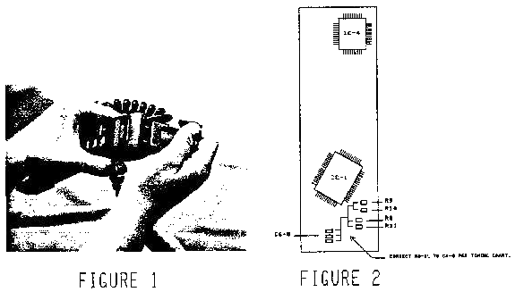
- At the bottom of the handset locate two small holes in the plastic molding
(see figure 1). Press a narrow alignment tool into both holes and pry the
handset apart (be careful not to break the short wires inside).
- Remove the PTT and AF level knobs.
- Remove the three 3 x 6 mm machine screws that secure the metal shield to
the handset.
- Lift the AF unit and shield to expose the Keyboard assembly.
- Locate resistors R8 - 11 on the Keyboard assembly (figure 2).
- Connect the left side of the resistor to the ground side (right side) of
capacitors C8 - 11. Use the timing chart and figure 2 for timing
configurations.
- Reassemble the handset. Route all wires under the cut outs on the shield.
Do not pinch any wires.

+------------------------------------------------------------------+
|               HANG UP TIME                        TIMEOUT TIMER  |
+------------------------------------------------------------------+
|                R10     R11                           R8      R9  |
|  0    SEC       0       0                 0 SEC       0       0  |
|  0.25 SEC       0       1                30 SEC       0       1  |
|  0.50 SEC       1       0                 1 MIN       1       0  |
|  3    SEC       1       1                 3 MIN       1       1  |
+------------------------------------------------------------------+
|                                    1: Do not connect to ground   |
|                                    0: Connect to ground          |
+------------------------------------------------------------------+

16-04-2000 RC-10 Alternator
noise
Author: Trio-Kenwood
Communication, inc.
Service Bulletin no. 927 (28-10-1988)
When two transceivers are connected to the RC-10, alternator noise may be
induced in the mic circuits. The following modification will correct this
condition.
Parts required:
600 ohm isolation transformer            W05-0222-00     qty 2.
470 µH ferri-inductor                    L40-471-05      qty 1.
- Remove the base plate from the RC-10 (6 screws on the plate; 1 screws on
the back panel).
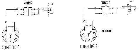
- Add the ferri-inductor between pins 7 and 8 of the connector B as shown
below.
- Locate connectors J2 on the AF unit (X49-3010-XX B/3).
- Add a transformer in each mic circuit as shown below.
- Using double sided tape, secure each transformer to the side wall on the
base.

This modification may be covered under warranty.
Time required for this
modification is ½ hour or less.


