Modifications for the Kenwood
SM-220

18-03-2000 SM-220 Shield
Installation
Author:
Trio-Kenwood Communication, inc.
Service Bulletin no. 57 (30-11-1979)
For Sweep interference from the SM-220 back into either a TS-520 or TS-180S,
install an additional shield in the RF compartment in the SM-220.
- Disconnect the power cord from the back of the scope.
- Remove the scope top cover.
- Loosen the function and RF ATT shaft couplers using a 1,5 mm allen key.
Withdraw the shafts away from the RF compartment.
- Remove RF compartment screws from the rear panel.
- Remove 4 screws to open the RF comp.
- Remove one screw to remove internal shield.
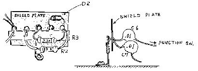
- C6, a .01uF. runs from the Function Switch to a ground point under the RF
ATT switch. Cut the ground lead and shorten so the cap is grounded to the
ground point under the Function Switch.
- R2, a 10 Kohm, is attached to the terminal strip directly under the
Function Switch. Reposition this resistor from the top of the terminal strip
the bottom of the strip.
- Install the additional shield to the ground point under the Function
Switch.
- Reverse disassembly procedure to reassemble.


18-03-2000 Feedback Between Pan display and
IF Out
Author: Trio-Kenwood
Communication, inc.
Service Bulletin no. 66 (25-7-1978)
We have found a few cases of feedback when the pan display option was
installed in the SM-220 Station Monitor. This is due to the isolated ground of
the BS-5 or BS-8 pan display option.
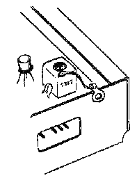
It may be remedied by grounding the case
of the input transformator in the BS-5 or BS-8 to the case. (See drawing below.)
This change will be incorporated in all future delivered of the BS-5 and BS-8.


