
When a plug other than the PG-2V or PG-3C is inserted into the DC IN jack, the ground side of the jack may not disconnect. This may cause the external DC power to be supplied directly to the internal battery which results in overheating the battery and blowing the fuse. To protect the battery, replace the fuse with a protection diode, part number ERB83-004.
Note models with serial numbers greater than 801XXXX allready incorporate this diode as D16.
This modification may be performed under warranty.
Time required for this
change is 1/2 hour or less.
19-07-1998 TH-215A to TNC
The
hook-up of a th-215a to my pac-comm tiny 2 tnc was very easy. There are no
components involved in the connection. All you need are two phone plugs: 1 sub
mini, and 1 stereo(3 conductor) mini.
Both available from radio shack,two to
a pack.
if you have a kenwood speaker mike, then the instruction sheet will
contain a drawing showing the basic connecting lines. if not, heres how its
done:
The sub-mini is the speaker plug. The center pin goes to the speaker
pin on the 5 pin din on the tnc, the shaft is the ground.
On the mini stereo
plug, you dont use the center pin, just the two shaft connections. the short
shaft goes to mike, the long shaft is the push to talk......thats it, four wires
to the connector that goes to the tnc plug, and youre in business!!
One
very very important thing-----always make sure that all battery save functions
on the handy talkie are off. if it isnt, a slight delay in receiving will cause
retrys from the station sending to you, and will delay packet reception at your
end. please make careful note of this. Any questions, reply to K2JOV, HARRY, at
N2ELC-4 BBS in n.j......good luck!!
19-07-1998 KENWOOD TH-215A out-of-band
mod
                              (top front inside)
                  +--------------------------------------+
                  |                                      |
                  |                                      |
                  |         +--------+                   |
                  |         |        |                   |
                  |         |        |                   |
                  |         +--------+                   |
                  |                                      |
                  |                      +--------+      |
                  |                      |        |      |
J4: intact        |           J4 o---o   |        |      |
J3: cut           |           J3 o) (o   +--------+      |
J2: cut           |           J2 o) (o                   |
J1: cut           |           J1 o) (o                   |
                  |                                      |
                  |                                      |
                  |                                      |
                  |                      SPKR            |
                  |                                      |
                  |                                      |
                  |             mic                      |
                  |                                      |
                  +--------------------------------------+
>In a sample population of about 60 amateurs in this town, three of us
>own Kenwood TH-215A HT's, all purchased separately at different times
>from different sources....

>ALL THREE have developed an audio problem in the last eight months:
>the audio (both from the microphone and from the keypad) simply
>disappears at unpredictable intervals.  And all three can be "fixed"
>by WHACKING the HT with the palm of one's hand--until it happens again.
A POSSIBLE FIX:
  J1  J2  J3  J4      RX           TX      step     DTMF     TONE
__________________________________________________________________________

  1   1   1   1    144-146Mhz     <==      20k       YES      38 tone

  1   1   1   0    141-163Mhz    144-146    5k       YES      38 tone

  0   1   1   1    144-146Mhz     <==       5k        NO      TONE1750hz

  1   0   1   1    144-146Mhz     <==       5k        NO      1750 hz

  0   1   1   0    144-146Mhz     <==      12.5k      NO      TONE/1750hz

  1   0   1   0    144-146Mhz     <==      12.5k      NO      1750 hz

  0   0   1   1    144-148Mhz     <==       5k       YES      38 tone

  1   1   0   1    141-163Mhz    144-148    5k       YES      38 tone

  0   1   0   1    141-163Mhz    141-151    5k       YES      38 tone

  0   0   0   1    141-163Mhz     <==       5k       YES      38 tone

  0   0   1   0    134-148Mhz     <==       5k       YES      38 tone

  1   0   0   1    154-174Mhz     <==       5k       YES      38 tone
0 = No jumper
The transceivers mentioned above can be mechanically improved by adding a bracket assembly to the volume and squelch controls. The bracket assembly is being used in current production and is available for older units from the Kenwood Parts Department.
Bracket Ass'y (W05-0235-00)
This modification may be covered under warranty.
Time required for this
modification is ½ hour or less.
16-04-2000 TH-215/415 TX signal-To-Noise
ratio improvements
Author:
Trio-Kenwood Communication, inc.
The TH-215/415 transmit signal-to-noise ratio is typically 30 dB. This ratio is more then sufficient for routine operations. For those users who would like to obtain additional performance, the following modification will provide an improvement of 5 to 8 dB.
Required parts:
47 ohm 1/10 watt chip resistor       (RK73FB2A470J)
220 ohm 1/10 watt carbon resistor    (RD14BB2B221J)
22 µF 6.3V Electrolytic capacitor    (CE04CW0J220M)
1 µF 50V Electrolytic capacitor      (C90-1248-05)

This is an optional change that may not be covered under warranty.
Time
required for this modification is 1 hour or less.
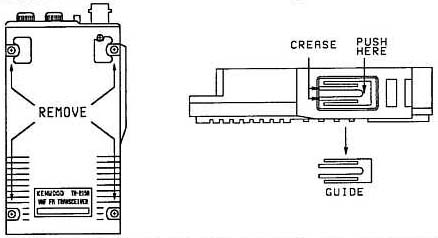
21-04-2000 TH-205/215/315/415 PTT knob
installation procedure
Author:
Kenwood Communication, inc.
The original plastic knob (K29-3054-15) has been replaced with a rubber knob (K29-3054-35). The PTT mounting guide on the front panel must be removed to allow the new knob to be installed. The following procedure will explain the installation procedure.