Modifications for the Kenwood
TH-26

19-07-1998 EXT TX ON THE:
TH-26AT/TH-45AT/TH-75A HT's
On the three above units a jumper
wire controls the TX frequency coverage. By removing the jumper you will extend
TX from 142-152Mhz.
By removing a diode you can extend the TX coverage to the
limits of the VCO. Both the jumper wire and the diode are located on the
"CONTROL UNIT".
On the TH-26AT this is just a bare jumper wire, TH-45AT
???, TH75A it is a green wire labled W1. Removing or lifting D4 on the TH-75A
extends TX from 136-174Mhz and 335-512Mhz.
On the TH-26/TH-46 models this
would be 136-174Mhz and 335-512Mhz respectivly.
28-08-1999 Expanding frequency range for the
TH-26E
Hello OM/YL,
Something on expanding frequency range
for Kenwood's TH26E.
To expand frequency range is very simple, you just have
to remove the little piece of wire called JP1 on the schematic diagram, it is
placed on the left side near the batterypack. This modification makes it
possible to transmit and receive over the range of 136.000MHz to
173.995Mhz.
Further expansion is not possible, the PLL doesn't lock anymore.
(expanding TX Frequency range outside 144 -146 Mhz is in some countries illegal
as we all know). It is also possible to expand RX only. To enable this hardware
modification is not nessecary!
Execute the following steps..
- Put the TH 26E into the VFO Mode
- Press the Call button,
- Keep the Call button pressed in and press the MR button also The decimal
point on the display will start to blink and when the TH 26E is in the 'beep
mode' it will also start to beep at a frequency of 1 Hz.
- Press the Call button, You will see that a frequency of 245.??? Mhz
appears, (the decimals are dependent of the value witch was inserted before
starting the programming...)
- Press the F key and load the 245.??? Mhz into the VFO..
- Switch your handheld transceiver off
- Press the REV button while turning the TH 26E on.. The Upper level of
frequency is now set to 245.??? Mhz
You must adjust the VFO lowest and
highest frequency according to your PLL lockingrange. My TH 26E PLL locks over a
range from 144.000 Mhz to 173.995Mhz. This software modification does not damage
the TH26E!
Only reception below 144.000 Mhz is not possible... You can set
the TH 26E into normal mode by resetting the VFO.
I'd like to know where
my message is received, and if you are succesfull modifying Your TH
26E...
Also I like to know if there are more intresting modifications on this
type of tranceiver. Please let me know!
Goodluck and '73 From Hengelo The
Netherlands JO32KG
Peter (PB0ANS @ PI8DAZ.nld.eu).
28-08-1999 Expanding frequency range for the
TH-26E
Author: Mathijs
PE1NTP
Schema Kenwood SMC 33 Handmicrofoon met A.B.
(c)
1992 Mathijs PE1NTP
21-04-2000 TH-26A Internal
bridges
Author: Kenwood
Communication, inc.
Service Bulletin no. 976 (8-8-1990)
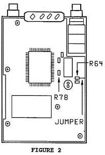
The TH-26A has two internal bridges. One is at 145.645 MHz and the other is
at 147.200 MHz. The first one is caused by the CPU clock and the second one is
caused by the PLL reference crystal. The bridge related to the CPU clock can be
corrected by changing R78 on the Control board from 3.9 Kohm to 6.8 Kohm and
adding a ground to R64. The birdie related to the reference crystal can be
corrected by changing L12 on the TX/RX (B/2) board from a 10 µH inductor to a 1
mH inductor.
Required parts:
RK73GB1J682J    6.8 Kohm chip resistor
L40-1021-14     1 mH inductor
To change R78:
- Disconnect the battery pack and antenna.
- Remove the three case screws and four battery plate screws. Figure
1.
- Lift the front panel from the body of the transceiver.
- Do not lose the rubber cover for the DC IN jack.
- Locate R78 on the Control board inside the front panel. Figure 2.
- Replace R78 with a 6.8 Kohm chip resistor.
- Install a jumper wire from R64 to the mounting plate behind the PTT
switch. Figure 2.
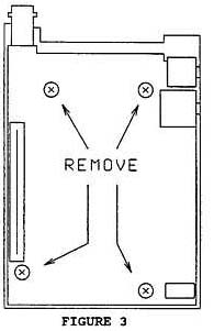
To change L12:
- Remove the four screws from the TX/RX (A/2) board. Figure 3.
- Carefully lift the TX/RX (A/2) board up and rotate it and the front panel
assembly to the right of the transceiver.
- Do not lose the rubber cover from the SPEAKER/MIC jack and the plastic
piece from the battery release.
- Remove the two screws from the power module shield and set the screws and
shield aside. Figure 4.
- Remove the four screws from the TX/RX (B/2) board. Figure 4.
- Remove the three black screws from the back panel that secure the antenna
BNC connector.
- Carefully lift the TX/RX (B/2) board off the back panel.
- Locate L12 on the TX/RX (B/2) board. Figure 4.
- Replace L12 with a 1 mH inductor.
- Assemble the transceiver.

Time required to perform this modification is 1 hour or less.