Modifications for the Kenwood
TH-415

16-04-2000 TH-205/215/415 Volume/squelch
control improvement
Author:
Trio-Kenwood Communication, inc.
Service Bulletin no. 944 (28-10-1988)
The transceivers mentioned above can be mechanically improved by adding a
bracket assembly to the volume and squelch controls. The bracket assembly is
being used in current production and is available for older units from the
Kenwood Parts Department.
Bracket Ass'y (W05-0235-00)
- Disconnect the battery pack and antenna.
- Remove the 7 screws from the panel of the transceiver (Figure 1).
- Lift the front panel from the transceiver and lay it to the right
side.
- Disconnect the 2 flex cables and remove the 3 screws from the IF unit
(Figure 2).
- Pull the top panel off and the remove the IF unit.
- Remove the knobs and black cloth from the volume and squelch
controls.
- Inspect the controls to insure they are mounted flush to the board. If
they are not flush, completely desolder and resolder the controls.
- Insert the bracket over the controls and tighten the nuts (tighten the nut
on the volume control first). See figure 3 for the bracket assembly
view.
- Assemble the transceiver be reversing steps 1 - 6.
This modification may be covered under warranty.
Time required for this
modification is ½ hour or less.
16-04-2000 TH-215/415 TX signal-To-Noise
ratio improvements
Author:
Trio-Kenwood Communication, inc.
Service Bulletin no. 946 (28-10-1988)
The TH-215/415 transmit signal-to-noise ratio is typically 30 dB. This ratio
is more then sufficient for routine operations. For those users who would like
to obtain additional performance, the following modification will provide an
improvement of 5 to 8 dB.
Required parts:
47 ohm 1/10 watt chip resistor       (RK73FB2A470J)
220 ohm 1/10 watt carbon resistor    (RD14BB2B221J)
22 µF 6.3V Electrolytic capacitor    (CE04CW0J220M)
1 µF 50V Electrolytic capacitor      (C90-1248-05)
- Disconnect the battery and antenna.
- Remove the 7 screws from the back panel of the transceiver (figure
1).
- Lift the front panel from the transceiver and lay it to the right
side.
- Disconnect the 2 flex cables and remove the 3 screws from the IF unit
(figure 2).
- Pull the top panel off and then remove the IF unit.
- Remove the 8 screws from the RF unit and unplug connector CN2 (figure 3).
Remove the RF unit from the back cover.
- Locate R50 (TH-215) or R60 TH-415) on the foil side of the RF unit (figure
4). Replace the resistor with a 47 ohm chip resistor.
- On the component side of the IF unit, add a 1 µF capacitor as shown in
figure 5.
- Also on the component side, cut one foil, add a 220 ohm resistor, and add
a 22 µF capacitor as shown in figure 6.
- Assemble the transceiver by reversing steps 1 - 6.
>
This is an optional change that may not be covered under warranty.
Time
required for this modification is 1 hour or less.
21-04-2000 TH-205/215/315/415 PTT knob
installation procedure
Author:
Kenwood Communication, inc.
Service Bulletin no. 987 (11-6-1991)
The original plastic knob (K29-3054-15) has been replaced with a rubber knob
(K29-3054-35). The PTT mounting guide on the front panel must be removed to
allow the new knob to be installed. The following procedure will explain the
installation procedure.
- Disconnect the battery pack and antenna.
- Remove the four screws from the back panel.
- Carefully lift the front panel up and lay it into the right side of the
body of the transceiver.
- Disconnect the front panel from the body of the transceiver.
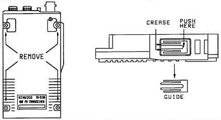
- The plastic PTT knob is held in place with three tabs. Press in the bottom
tab and then push the knob out of the front panel.
- Push in the guide to crease it's two legs where they join the front
panel.
- Wiggle the guide back and forth until it breaks off the front panel.
Discard the guide and plastic knob.
- Install the rubber knob on the front panel. The side with the square tab
goes toward the bottom of the front panel.