Modifications for the Kenwood
TM-631

21-04-2000 TM-631/731A Memory loss
modification
Author: Kenwood
Communication, inc.
Service Bulletin no. 972 (8-8-1990)
Some TM-631/731A owners have reported that the transceiver intermittently
loses its memory channel information when the power switch is turned on. The
following modification will absorb pulses on the CPU interrupt line (INT4) and
reconfigure the backup switching circuit to avoid unintentional memory loss.
Read all instructions before proceeding. Do not attempt this modification if
it is beyond your capability.
Required parts: ZKIT-731MEMO
The kit contains:
Part #                Description                                   QTY.
NJM78L06A             6 V AVR                                         1
1SS133                Diode                                           1
MTZ3.0JB              3.0 V Zener diode                               1
CE04NW0J221M          220 µF, 6.3 V Electrolytic capacitor            1
C91-0457-05           0.022 µF ceramic capacitor                      1
CK45B1H103K           0.01 µF ceramic capacitor                       1
RD14BB2C103J          10 Kohm, 1/6 watt resistor                      1
RD14BB2C102J          1 Kohm, 1/6 watt resistor                       1
RD14BB2C472J          4.7 Kohm, 1/6 watt resistor                     1
RD73FB2A472J          4.7 Kohm, 1/10 watt resistor                    2
- Disconnect the power supply, antenna, and microphone.
- Remove the top and bottom covers (12 screws). Do not damage the speaker
wires when removing the top cover.
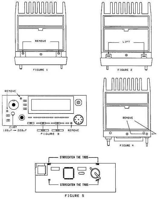
- Pull the Main Encode, Volume, and Main Squelch knobs off the front panel.
If a knob does not easily pull off, wrap a cloth around the knob and carefully
pull it off with a pair of pliers. Be careful not to crush or scar the
knob.
- Remove the two brass colored screws from the top of the plastic front
panel. Figure 1.
- Gently lift the two tabs on the bottom of the front panel and then pull
the front panel off the transceiver. Figure 2.
- Remove the two black shades from the Balance and Sub-Squelch controls.
Figure 3.
- Remove the three brass colored screws from Control board B/3. Figure
3.
- Remove the brass colored screw that is mounted on the front panel chassis
above the Power switch. Figure 4.
- Remove the brass colored screw that is mounted on the front panel chassis
to the right of the microphone jack. Figure 4.
- Carefully pull Control board (B/3) away from the body of the
transceiver.
- Disconnect the two "wire type" cables from the body of the
transceiver.
- Disconnect the two flex cables from the Control board. The flex cables
simply pull out of the connectors.
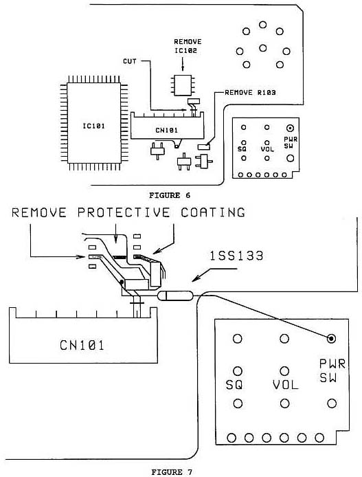
- Remove IC102 from the Control board. Since this device is glued to the
board, use a needle tip tool to lift each pin as you melt the solder. Then pry
the chip off the board with a craft knife. Figure 6.
- Remove any excess glue and solder from the area where IC102 was
located.
- Remove chip resistor R103. Do not melt connector CN101. Figure 6.
- Cut the foil pattern between connector CN101 and chip capacitor C102. Make
the cut as close to connector CN101 as possible. Figure 6.
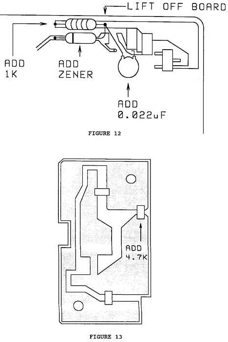
- Prepare the 1SS133 diode for installation. The cathode lead will be cut
and bent 90°. The diode must lay flat on the board and the cathode lead cannot
touch the cut in foil. Once the diode leads are prepared, solder the diode in
place. Figure 7.
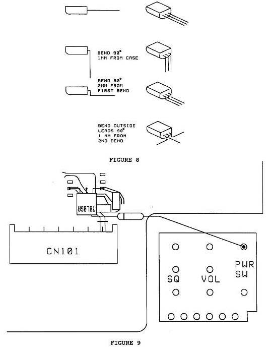
- Prepare the NJM78L06A 6 V AVR for installation as shown in figure 8. The
leads to this device are vary soft and can break when bent too often. Make
each bend only once.
- The 6 V AVR will be mounted in place where IC102 was located. The board
must first be prepared for the installation. Remove the protective coating
from the foils as shown in Figure 7. These are the foils that where connected
to pins 2 and 7 of IC102 and the ground foil that runs under the
device.
- Place the 6 V AVR on the board and make sure the leads contact the foils.
Cut the leads to size and then solder the device to the board. Figure
9.
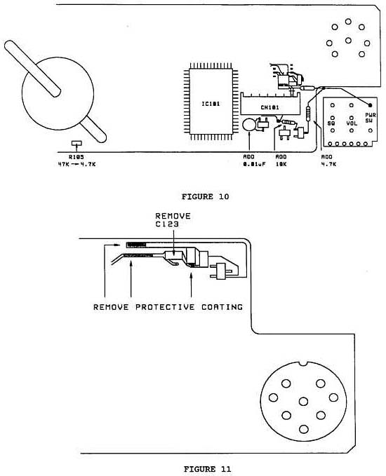
- Prepare the 0.01 µF capacitor, 10 Kohm resistor, and 4.7 Kohm resistor for
installation. Place the parts on the board to size and cut the leads. Once the
parts are prepared, solder them to the board. Figure 10.
- Locate R105. If the component is 47 Kohm, change it to a 4.7 Kohm chip
resistor. The component's value can be determined by the numbers written on
the case. If the device is labeled 473, it is a 47 Kohm resistor and needs to
be replaced. If the device is labeled 472, it is a 4.7 Kohm resistor and does
not need to be replaced. Figure 10.
- Straighten the tabs that hold the LCD assembly to the…………. The rest of the
composing is missing, mail me if you have
it.
- This point is missing, please mail me if
you have this.
- This point is missing, please mail me if
you have this.
- This point is missing, please mail me if
you have this.
- This point is missing, please mail me if
you have this.
- This point is missing, please mail me if
you have this.
- This point is missing, please mail me if
you have this.
- This point is missing, please mail me if
you have this.
- This point is missing, please mail me if
you have this.
- This point is missing, please mail me if
you have this.
- This point is missing, please mail me if
you have this.
- This point is missing, please mail me if
you have this.
- This point is missing, please mail me if
you have this.
- This point is missing, please mail me if
you have this.
- This point is missing, please mail me if
you have this.
- Slide the lock, balance, and Sub-Squelch controls to the left.
- Slide the Lock, Balance, and Sub-Squelch knobs on the plastic front panel
to the left.
- Gently install the plastic front panel on the front panel assembly. Do not
force the installation.
- Install the two brass colored screws on the top of the plastic front
panel.
- Install the Main Encode, Volume, and Main Squelch knobs.
- Remove the two screws from the small board where the positive power lead
connects on the bottom of the transceiver.
- Solder the remaining 4.7 Kohm chip resistor to the foil side of the board.
Figure 13.
- Mount the board and install the covers on the transceiver.

This modification may be covered under warranty.
Time required to perform
this modification is 1 hour or less.
21-04-2000 TM-731A/631A Final board C17
change
Author: Kenwood
Communication, inc.
Service Bulletin no. 977 (8-8-1990)
Bypass capacitor C17 on the 144 MHz Final board has been changed in
production from a "flat package" chip capacitor to a "cylindrical package". The
change prevents the capacitor from fracturing. If C17 fractures, the output of
the power module can burn C17, R11, and L6. Additionally, Q1 on the TX/RX 144
MHz board may be damaged.
C17 should be changed as a part of routine maintenance when a TM-731A/631A is
received for service. The new style capacitor part number is CK41FY1E102M. For
field service, a 0.001 µF, 25 V disc ceramic capacitor can be used.
The production change started at serial number 108xxxx.
To replace C17:
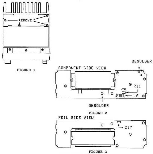
- Disconnect the power supply and antenna.
- Remove the top cover. Do not damage the speaker wires.
- Remove the shield plate from the VHF Final unit (4 screws). Figure
1.
- Remove the 7 screws that secure the final board to the chassis. Figure
2.
- Remove the 2 screws that secure the power module to the chassis. Figure
2.
- Remove the 2 screws that secure the VHF antenna coax to the heat
sink.
- Desolder the center conductor and shield of the VHF antenna coax from the
final board and pull the coax out of the heat sink. Figure 2.
- Desolder the terminal next to pin 3 of the power module. Figure 2.
- Rotate the board toward the front of the transceiver to expose the foil
side of the board.
- Inspect the solder at the terminals the antenna coax was soldered to. They
may need to be resoldered.
- Replace C17. Figure 3.
- If you are serving a TM-731A/631A that has been damage, check R11 and L6.
The coil may have pin hole burn marks in its insulation and the resistor may
be open. In addition, check Q1 on the RX/TX (144 MHz) board. If it is damage,
the receiver sensitivity will be low.
- If the Final board has been burned, it can be repaired. The carbon must be
completely removed from the board to prevent the board from burning any
further (carbon tracking of the RF signal). The burned area should be filled
with epoxy an the lands must be repaired.
This modification may be covered under warranty during the warranty
period.
Time required to perform this modification is 1 hour or
less.