
19-07-1998 TM-701A repeater cross-band
modification
Perform the following modifications to allow the
TM-701A to operate in the repeater cross-band
mode.
MODIFICATION:
- Disconnect the power supply and antenna.
- Remove the top and bottom covers (12 screws). Disconnect the speaker wire
from the transceiver.
- Locate the green jumper wire show in figure 1. Using a sharp pair of wire
cutters, cut the jumper in half.(green jumper)
______
______________ | |_____
| TOP <|---- Green Jumper
| |
| |
| Heat sink |
| | |
|
/
figure 1
CAUTION:
Cutting the green jumper allows the TM-701A to transmit from
142 to 151.995 MHZ. Protect your license by only using frequencies that you
are authorized to transmit on.
- Solder a jumper wire to the foil side of the TX-RX board as shown in
figure 2.
______ ^
__| |________|________________
| Display side |
| X ...... | X = Screw
| X ...... |
| - ----| |
| .............. | <---------- ADD Jumper
. |
Pin #3 :____________|
:
figure 2
- Assemble the transceiver by reversing steps 1 -2.
- Reset the microprocessor by holding in the MR key as the power is turned
on.
The repeater cross-band operation allows the TM-701a to receive on
one band and re-transmit the signal on the other band. The TM-701a alternately
displays the two bands until a signal is received. The transceiver will then
display the band that is re-transmitting the signal. The SHIFT function cannot
be used during the repeater cross- band operation. If the TONE or CTCSS function
is required, only one ETA tone can be used for the two
bands.
OPERATING PROCEDURE
- Select the operating frequencies for both bands.
- Set the squelch control to the threshold point. The TM-701a will transmit
in the repeater cross-band mode if the squelch control is set too low or a
signal is received.
- Place the transceiver in the duplex mode (F + DUP).
- Press the F key for longer than one second. The F indicator will flash.
- Press the LOW key. The transceiver will now enter the repeater cross-band
mode of operation.
- To cancel the operation and return to the VFO mode, press the VFO key.
Figure 2
rear of radio
------------------------------------------------------
! !
! !
! o !
! o !
! o !
! o !
! o o !
! o o !
! o o !
! o o !
! o o !
! __add__________Xo !
! i o !
! i o !
! i !
! i ooooooooooooooooooooooooooooooo !
! i !
! -------i !
! i !
! Xo@o !
! !
! ooooooooooooooo !
! oooooooooooooooooooo !
_____________________________________________________
mic plug (radio bottom)
(Jumper wire from X to X)

19-07-1998 TM-701
transmitting and receiving from 136-175MHz
The Kenwood TM-701 A
is capable of transmitting and receiving from 136-175 MHz. and from 340-512 MHz.
when the following mods.
Cut the GREEN jumper wire on the Control PC
Board behind the front panel.
The control PCB # is X57-3350-00. Add Diode
D207 and D 209 (1ss181 or equiv) a 1n914 should work fine. Anode goes to the
switches and the cathode to the IC (IC201).
2. Reset the microprocessor
by holding in the "MR" key as the power is turned on.
to access the
Control PCB:
- remove top bottom covers.
- remove knobs pulling them straight off of the front panel.
- Remove plastic faceplate.
- remove 4 screws on front panel metal spacer and remove panel.
- remove plastic panel/LCD by pulling straight off of the rig toward front.
- remove the 3 screws from the Control PCB and pull straight off of the
chassis.
- Diodes mount on the back of the PCB at S205 and S209. The Andoe goes
toward the switches and the cathode goes away from the switches.
D209 goes
to S205 (TONE switch)
D207 goes to S209 (MR switch)
D208 goes to S204
CAUTION remove D208 only if you want to change the split from +- 5 Mc to +-
1.6 and - y6 Mc (european split).
replace all parts in reverse order. There
is no RF circuit adjustments needed for this mod.
If there are any
questions please call me at N4LDG PBBS Miami or write me at 11102 S.W. 117
Street Miami, Fl 33176 Hope you can now enjoy a nice rig!
John KA4ZAY
Miami

20-04-2000 TM-701A
Intermittent memory loss
Author:
Trio-Kenwood Communication, inc.
Service Bulletin no. 966 (4-4-1990)
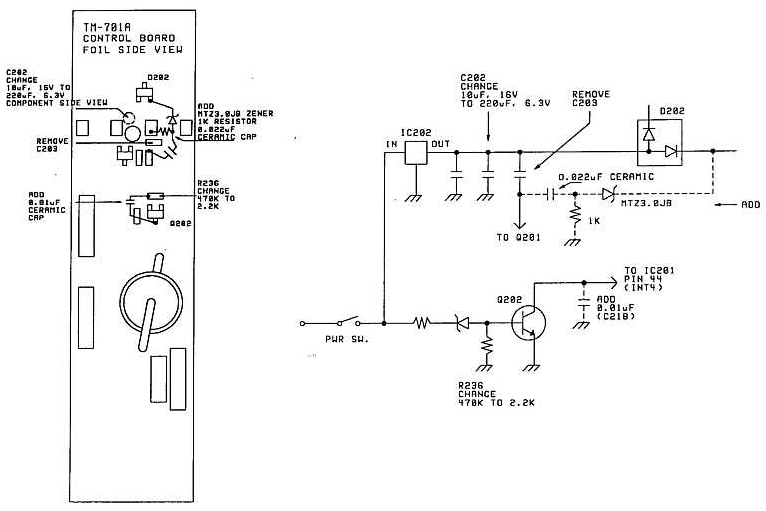
Some TM-231A owners have reported that the transceiver intermittently loses
its memory channel information at power on. The following modification will
absorb pulses on the CPU interrupt line (INT4) and reconfigure the backup
switching circuit to avoid unintentional memory loss.
This modification should be performed on a Dealer level as they have the
correct tools to disassemble the transceiver.
Required parts:
220 µF, 6.3 V Electrolytic capacitor CE04NW0J221M
0.01 µF ceramic capacitor CK45B1H103K
0.022 µF ceramic capacitor C91-0475-05
2.2 Kohm chip resistor RK73FB2A222J
1 Kohm carbon resistor RD14BB2C102J
3.0 V Zener diode MTZ3.0JB
- Disconnect the power supply, antenna, and microphone.
- Remove the top and bottom covers (12 screws). Disconnect the speaker plug
when the top cover is removed
- Remove the knobs from the front panel.
- Remove the nut from the microphone jack and the 11mm nut from the channel
selector switch.
- Remove the 4 screws that secure the front panel to the body of the
transceiver.
- Pull the front panel off the transceiver to expose the Control
board.
- Remove the 3 screws from the Control board. Gently pull the board off the
transceiver.
- Perform the changes shown in the accompany diagram. C202 is on the
component side of the Control board. All other work will be done on the foil
side of the board.
This modification may be covered under warranty.
Time required to perform
the modification is 1 hour or less.
