Modifications for the Kenwood
TR-2600

19-07-1998 Extended
frequency TR-2600A
Here is some info on the kenwood model
tr-2600a handie - talkie....
If you want to be able to transmit on the
extended freq area then do the following mod....
- Remove the front cover of the radio
- Locate the ic chip in the lower right hand corner.
- Find the 2 diodes number d32 and d33 (they should be the top two on the
right side of the ic chip, also they have ben cut beforenand (re-soldered)
- Un-solder the two diodes (breaking their connection).
- Replace the front ctver.
- Re-install the battery and turn the unit on, then push the reset button on
the back.
The tr-2600a should now be reprogramed and it should also
transmit anywhere it will recieve...
I forgot to add that d32 and d33 on
the recieve board (but that is what is under the front cover).
Jim -
KD0PJ

19-07-1998 TR-2600A
PLL Unlock Troubleshooting
Author: Trio-Kenwood Communication,
inc.
Service Bulletin no. 901 (18-10-1985)
The owners manual for the TR-2600A lists the lithium battery as a possible
cause of the display showing UL. You may wish to check the battery, but
realistically on a new radio this is probably not the reason for the unlock
condition.
If the radio showl UL when first turned on you should perform the following
test. This will help you to isolate the symptom:
- With the radio turned OFF, press and hold the 5 key, and then turn on the
radio. Release the 5 key. If the display shows a frequency indication you may
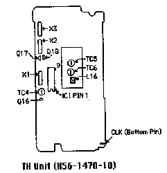
have a pad X2 on the TX unit.
- If there is no frequency display other than UL then proceed with step
II.
- You may also wish to check crystal X1 the Reference oscillator (10.240 MHz
at pin 16 or 17 of IC1.)
There are several other points to check.
- Check trimmer capacitors TC , TC5 and TC6. If you press on the trimmer and
the UL dissappears replace the trimmer.
- Check pin number 18 of IC1, it should be 5.4 - 6 vdc.
- If the voltage is over 6.5vdc replace Q17, Q18, and IC1.
- If the voltage is less than 5vdc replace Q17 and Q18.
- Check the CLK signal at the flex pc board connector, and pin 10 of IC1.
- The CLK signal should be aprox 4 - 4.4 vdc.
Pin 10 should be aprx. 0
- .2 vdc.
- If pin 10 is high check Q16, and for cold soldering on the flexible pc
board between the keyboard and the RX unit.
- Check the alignment of the PLL section, as given in the Service
manual.
- Press the RESET pushbutton on the back of the radio.

Time required for this modification is 1/2 hour or less.

19-07-1998 How to fix
TR-2600 keypad
I have a TR-2600, and a few years ago the keypad
failed. The symptom was that buttons in one column of the pad did not work. I
opened the radio up hoping to find a loose wire that I could re-attach--no such
luck.
The "keypad" is a PC board mounted directly behind the buttons.
There are several diodes (and little else) on the board. I checked the diode
closest to the affected buttons, and it had failed. Once it was replaced with a
garden-variety switching diode, the radio worked fine. So, a new keypad may not
be necessary. I hope this helps.

15-04-2000 TR-2600A
PLL unlock
Author: Trio-Kenwood
Communication, inc.
Service Bulletin no. 903 (14-1-1986)
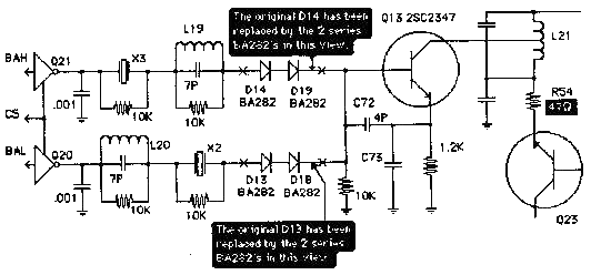
Some cases of PLL on the TR-2600A may be caused a failure of the crystal
oscillator circuit X2, X3, and Q13. This may be corrected by performing the
following changes.
On the TX unit (X56-1470-10)
Replace Diodes D13, and D14 (MA856) with a series pair of BA282's as shown in
the diagram below. Also change resistor R54 to 47 ohm as shown.
Parts required:
BA-282 diode, 4 each.
47 ohm chip resistor (RD73FB2A470J), 1 each.

This change is applicable to serial numbers before SN 702xxxx.
Time
required for this modification is 1 hour or less.


