Modifications for the Kenwood
TR-7400

19-07-1998 Service
Notes on TR-7400A
Author:
Trio-Kenwood Communication, inc.
Service bulletin no. 18 (6-10-1977)
PLL and LED
Display
- No transmit or PLL unlock light on: R-27 shorted to shield at D-1 on VCO
Unit (X50-1370-10).
- LED display changes when pushing on LED boards: Remove LED display boards
on display mother board. Trim all wires as close to the circuit board as
possible. Insulate the foil side of the board with thin plastic and reinstall.
- PLL unlock light on: Check for 9 volts at 9V terminal on VCO Unit
(X50-1370-10). Check Q10 (2SC496) and zener D5 (WZ-061) on this board.
- PLL unlock light on and no signal at PI terminal on PD Unit (X50-1380-
10): Check for open ferri-inductor L1 in emitter lead of Q1 on VCO Unit
(X50-1370-10).
- PLL unlock light on and no signal at pin 3 of IC4 on PD Unit (X50-
1380-10): Check for proper divide down signals on IC10, 5, 6, 7, 8.
- Digits in display are intermittent or some segments are not properly lit:
Reseat the connectors on the Display Unit (X54-1210-10). (Push them with a
small screw driver.)
- PLL unlock light stays on when unit is first turned on or cold: Change R4
on the PD Unit (X50-1380-10) from 470 ohms to 47 ohms.
- PLL unlock light is on for about 2 minutes when the unit is first turned
on and the inputs to IC4 on the PD Unit are ok, but there is no output:
Defective IC-4.
- LED display changes when slightly turning or pressing down on channel
select knobs: Check for loose solder connections on the circuit board under
the BCD switches. (ON bottom of unit.)
- One segement of one LED is dim: LED may be defective or the resistor
network may not be properly soldered.
- Speaker howl at high volume levels: Reseal the VCO coil (inside small
shield box) on the VCO unit (X50-1370-10). use Q dope or a small amount of
Epoxy glue. The VCO must be retuned after the glue dries.
- -600 KHz offset does not work: Check for open ferri-inductor L1 on PD unit
(X50-1380-10)
- LR frequency cannot be adjusted to meet specifications: Check for proper
frequency at TP1 on the PD unit. It should be 2.56000MHz. (Must use a 33 pf
capacitor when counting this frequency)
Receiver
- Receiver sensitivity down 30db: Check voltage at the drain of Q1 (3SK41L)
on the RX Unit (X55-1150-10). It should be 7 volts. If it is "0vdc", check for
shorted feet-thru capacitor in the helical resonator. It may be necessary to
replace the helical resonator.
- No receive: Check C9 voltage. Q27 (CSC496) on RX unit may be defective.
- No receive and no C9 voltage: Check Q28 (CSC496) and zener D16 (WZ090) on
the RX unit.
- Intermittent receiver audio: Check for shorted terminals on the volume and
squelch controls.
- Receiver sensitivity down: Check for proper level of LR signal. If down,
check diode D-6 (1S2588) on the VCO Unit (X50-1370-10).
- Receiver audio jumping up and down: Check C59 and C62 on RX unit.
- No receive or low sensitivity: Check for proper output of 10.245MHz
oscillator. The 10. 245 MHz crystal may be defective.
- Intermittent receive: Check discriminator colil L14 on RX Unit. It may be
open.
- Meter lamp out: Replace small lamp (B30-9996-05) as follows:
     1.  Remove meter
     2.  Remove wires
     3.  Remove small circuit board
     4.  Replace lamp
     5.  Reassemble
Transmitter
- No meter indication but output power OK: Check for broken wire at terminal
SM1 on the RX Unit.
- Transmitter intermittent when keyed rapidly: Defective D3 (MI402) on PA
unit (X45-1090-10).
- Position of L2 in PA unit: The proper position of this coil is directly on
the collector tabs of Q2 (2N6083). This applies to 45XXXX serial numbers only.
- Background noise on transmit: Reverse coil L1 on the TX unit (X56-
1230-10).
- RF meter works when first key transmitter an then fails: Check for pinched
RF sens wire at coil L7 in PA unit. Widen this coil if necessary.
- Transmitter off frequency and receiver on frequency: Adjust coil L3 on TX
Unit for correct frequency.
- No RF output: Diode D3 (MI402) in PA unit shorted or improperly soldered.
If this diode is replaced, keep the leads as short as possible an build up
solder on the foil side of the board.
- Low output power: Loose connection at TC3 in PA Unit.
- No RF output and receiver sensitivity dow 30db: Diode D2 (MI301) on the PA
Unit may be defective. Also check D3 (MI402) on this board. Q1 (3SK41L) on the
RX unit may also be defective.
- Intermittent or no transmit: Check for loose connection at Q15 (2SC908) on
the TX Unit. Also check the heat sink for this transistor.
- No RF output but drive to PA Unit is OK: Check for proper SB voltage. It
should be 11 to 12 vdc when transmitteing into a 50 ohm load. If it is 0vdc
check Q10 (2SC496) on the TX Unit.
- No Modulation: Capacitor C4 (0.1 ufd tantalum) on TX unit may be open.
- No modulation: Check for pinched pins at microphone jack.
- No RF output on one band: Check for proper alignment of potentiometers
VR61, 62, and 63.
- No RF output: L4 not soldered to base of Q4 (2SC458B) in PA Unit.
13-02-2000 Arcing in
TR-7400A final section
Author:
Trio-Kenwood Communication, inc.
Service bulletin no. 10 (13-1-1977)
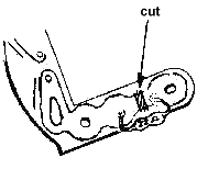
There may be some cases of arcing to ground beneath coil L-6 at the collector
of Q-2 (2N6083) inside the final unit X45-10-90-10.
This is due to minute
differences in the circuit board trace dimensions and a residue af flux on the
board.
If this should occur, remove L-6 and clean all traces of carbon and flux from
the circuit board. Resolder the edges of the tracer and remove any flux left
from soldering. Modify L-6 as shown:

reinstall L-6 and check for rated output. A slight retuning of TC-4 may be
required.
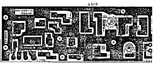
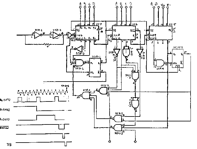
20-02-2000 Changes in
PO Unit of the TR-7400A
Author:
Trio-Kenwood Communication, inc.
Service bulletin no. 32 (19-1-1979)
There was a temporary production change in the PO Unit of the TR-7400A. This
change effected the 73XXXX and 74XXXX series units only. The change was made
because of the Motorola MC-4016P IC was not available. The Texas Instruments
SN74LS192 IC was used as a replacement. It is not a direct replacement, though.
It was also necessary to change IC-8 from a TD-3400AP to a TD3404. This series
of PO Units is easily recongnized because of the three SN74LS192 IS's are
mounted in sockest instead of being soldered in place. The PC board was changed
to J25-2512-03T instead of J25-2512-03 for this change. The schematic is shown
below.
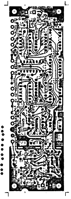
20-02-2000 Making
meter lamp in TR-7400A last longer
Author: Trio-Kenwood Communication,
inc.
Service bulletin no. 34 (15-5-1979)
The life of the meter Lamp in the TR-7400A may be extended by inserting a
22ohm 1/4W resistor in series it. This resistor may be conveniently mounted on
the circuit board that holds the lamp by cutting foil path on one side of the
lamp and soldering the resistor across the break in the foil path. A drawing of
the circuit board with the resistor added is shown below.