Modifications for the Kenwood
TR-7850

19-07-1998 TR-7850 RF
LED Meter
Author: Trio-Kenwood
Communication, inc.
Service Bulletin no. 846 (29-7-1981)
The RF LEd meter may show reduced output after continuous transmission, while
output actually remains constant. Changing components on the final unit will
correct this problem. This change applies to units before serial number 201XXXX.
Procedure:
- Remove the top cover (four screws), and unplug the speaker.
- Remove the bottom cover (four screws).
- Remove four scress holding the heatsink and swing the sink down.
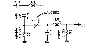
- Without changing coil spacing, desolder L6 which connects from the ANT pad
aon the final unit to the PL-259, at the final unit.
- Remove five screws holding the final unit pcb X45-1180-10, one screw
holding Q6 2SD880, and two screws holding the final hybrid module Q1, M57726.
- Change the following parts:
C15 1pf to 2pf (CC45CH1H020C)
D3
1N60 to 1S1587 (V11-0370-05)
R8 820 ohm to 1.2K (RD14CD2E122J)
- Insure adequate thermal compound on Q1 and Q6, and that the mica washer is
correctly positioned under Q6. Reverse steps 5 and 4 to partially assemble.
- Cable-up power and a dummy load. Readjust VR1 on the final unit at 147.000
MHz, high power setting for 5 LED's ON. Switch to low power and verify 3 LEDs
ON.
- Remove power from the unit and complete reassebly by reversing steps 3, 2,
and 1.

Note: installation time for this procedure is 1/2 hour or less.

08-04-2000 Memory
Channel 7 Indicator Erratic
Author: Trio-Kenwood Communication,
inc.
Service Bulletin no. 860 (14-4-1982)
When Memory Channel 7 is selected, the LED may fail to indicate the number 7,
although frequency is correctly recalled and all other operations are normal.
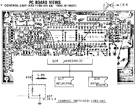
Cause is incorrect voltage level at Q16 & Q17, and is related to individual
differences between these IC's. Correction is by changing one resistor value on
the control unit.
On the control unit X53-1130-xx, replace R38 from 3.9 Kohm to a 1.8 Kohm
resistor (RD14CB2E182J). No adjustments are required.
This change should be perform only as necessary, and applies to units before
serial number 205xxxx.

Installation time for this procedure is ½ hour or less.

08-04-2000 TR-7800,
TR-7850 Memory Improvements
Author: Trio-Kenwood Communication,
inc.
Service Bulletin no. 861 (5-4-1982)
TR-7800 & TR-7850 memory retention may be improved by the following
changes on the control and RX units.
Control unit X53-1180-xx
- If not already present, add a 470 Kohm ½W resistor (RD14BB2B474J) (R54) on
the foil side of the board from connector 11 UP line to ground. (Unite before
serial number 1119391).
- If not already present, add a 470 Kohm ½W resistor (RD14BB2B474J) (R55) on
the foil side of the board connector 11 DOWN line to ground. (Unite before
serial number 1119391).
- Hard-wire the two via holes (through hole without components leads
installed) along the foil trace between Q18 pin 1 and L1.
- Change D1 from an ZX-060 (6V, 5%) to a WZ-040 (VII-4102-40) (4V, 10%)
Zener.
- Check D3 for leakage, which would load the MB line voltage below it normal
5.2 V DC setting.
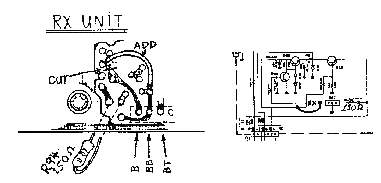
RX unit X55-1270-xx
- TR-7800: Change R94 from 56 ohm to 150 ohm ½W (RD14CB2E151J).
- TR-7850: Change R94 from 100 ohm to 150 ohm ½W (RD14CB2E151J).
- Cut the foil at the input to Q27, and connect Q27 input to the BB
terminal. Connector 1 for constant battery charge at Power switch Off, and
floating battery charge when using a TK-1 or BC-1 charger unit for memory
back-up in base station operation.
- Check D18 for leakage, loading the MB line.

Note:
- With 13.8V DC applied to the radio, and the power switch OFF, adjust VR2
on the RX unit for 5.2V DC at connector 1, MB terminal.
- We recommend using either Sanyo or GE NiCad Batteries. We suggest not
using Radio Shack or Eveready batteries in these radios.
- If memory loss persists after all changes and checks suspect control unit
Q18 is defective.


