Iulian Rosu, YO3DAC / VA3IUL - http://www.qsl.net/va3iul/
This Spectrum Analyzer supposes to be a cheap and
a useful device for any ham radio. To build this device you need minimum test
equipment, like a digital counter, an oscilloscope, Grid-meter and a multi-meter.
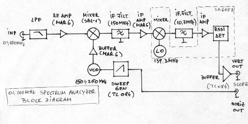
The main design is based on SA605D, FM receiver from
Philips.
This circuit is very common in some old analog cell phones.
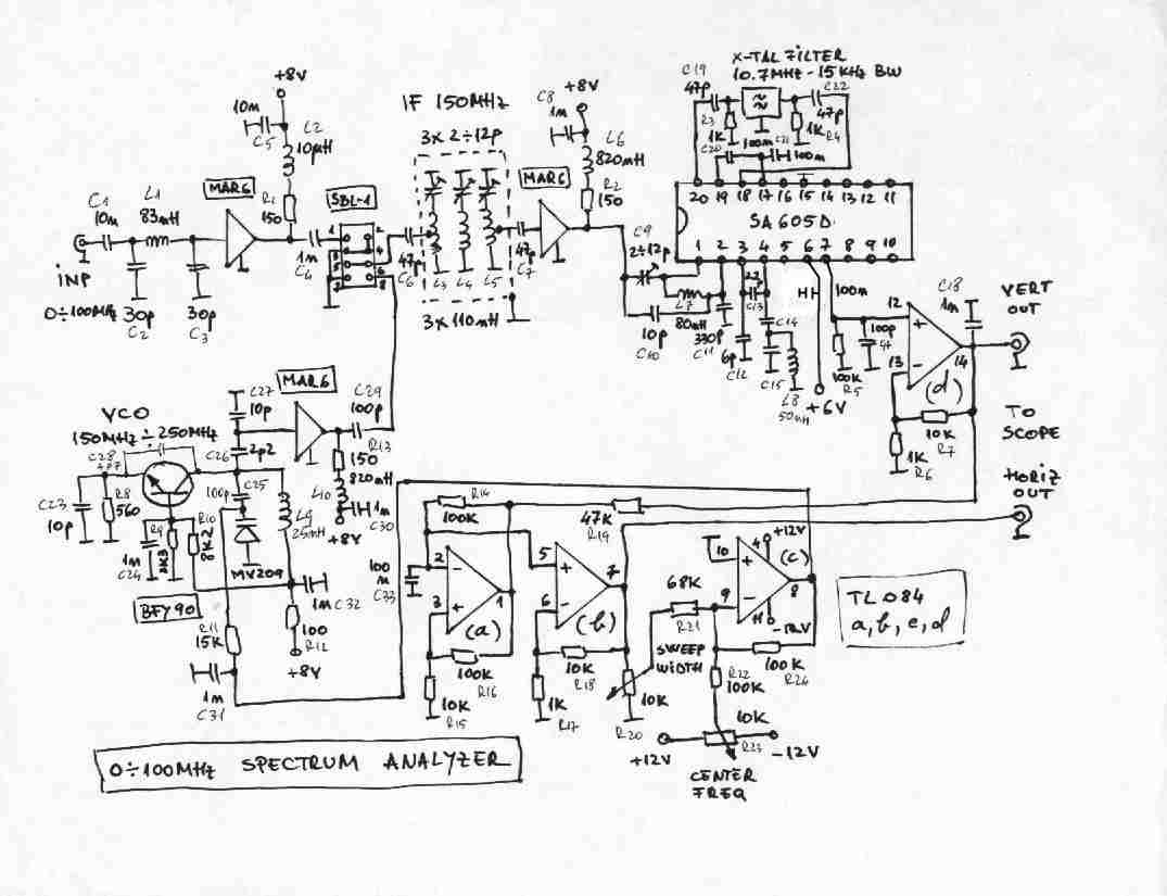
If we take a look to the main schematic, we
can see that the input signal pass through a low-pass filter (L1, C2, C3),
and it is amplified by a MMIC,
MAR-6, in order to boost the weak signal
performance of the instrument.
It is important to remember never to exceed the
maximum input level specification of the Spectrum Analyzer. Do not confuse
the maximum input level specification with the 1dB-compression point or
third-order intercept point specification. The maximum input level specification
is the maximum input level that will not damage the amplifier or mixer.
The 1dB compression point or third-order intercept point refers to distortion
caused by excessive input levels. The third-order intercept point usually
occurs about 10dB-15dB above the 1dB-compression point. If an analyzer
specifies the 1dB-compression point as 0dBm, then input levels higher than
0dBm should not be present at the output of the RF attenuator. If the RF
attenuation is set for 20dB, then the input level (at the input connector)
may be as high as +20dBm without exceeding the 1dB-compression point. It
is always best to allow an extra few decibels of safety margin. For example,
if the 1dB-compression point is 0dBm, then the input level should be kept
several decibels below this point for best performance.
If we check Minicircuits catalogue we can find that the 1 dB compression
point for MAR-6 is 2dBm with a gain of 20dB at 100MHz. But in the same time
the SBL-1 mixer support on its RF input signals only up to 9dBm. So in
our case, the limit of input signals will be around 10dBm, to keep a good
linearity of our measurements.
The range of the VCO, used to down convert
the signal to first IF, is from 150MHz to 250MHz. The VCO can use any NPN RF transistor, like BFY90, BFR90
etc. The varicap diode should be MV209 or an equivalent diode, which can
give a good, voltage versus capacity linearity. L9 from the tank circuit
has 3 turns, on 3mm diameter and 5mm length. With a frequency counter connected
to pin 8 of SBL-1 you can measure and adjust the frequency range of the
VCO.
On the output of the SBL-1 mixer, we have the first IF filter on 150MHz.
The bandwidth of this filter is 1MHz. Each inductor of the filter has 5 turns, 1mm silver plated wire, on
8mm diameter and 10mm length. The trimmer capacitors
(2-12pF) are used to tune the filter. Another MAR6 is used to amplify the
first IF signal.
The circuit SA605D is a high performance monolithic
FM system incorporating a mixer/oscillator, two limiting amplifiers, quadrature
detector, logarithmic received signal strength indicator (RSSI).
The input match of SA605D is C9, C10 and L7. The
tank circuit of the 139.3MHz LO (used to down convert the signal to second
IF) is C12, C13, C15, L8. L8 has 6 turns, on 4mm diameter. Check for the
right LO frequency on pin nr 4. For a better frequency stability you can
use a 139.3MHz crystal oscillator. The second IF is 10.7MHz. I chose this
frequency because here we can find plenty of IF filters. The main schematic
use only one X-tal filter, which will give to the analyzer a 15kHz RBW
(resolution bandwidth). Its possible to use here switched filters, for
different RBW. For 3kHz RBW, is possible to use a SSB filter and for 150kHz
RBW, ceramic filters used in broadcast FM radios.
One of the most important part of SA605D is the
RSSI indicator, that will be our logarithmic detector. You can see the
RSSI vs Input level graph in
SA605D Datasheet
and
SA605D Application Note.
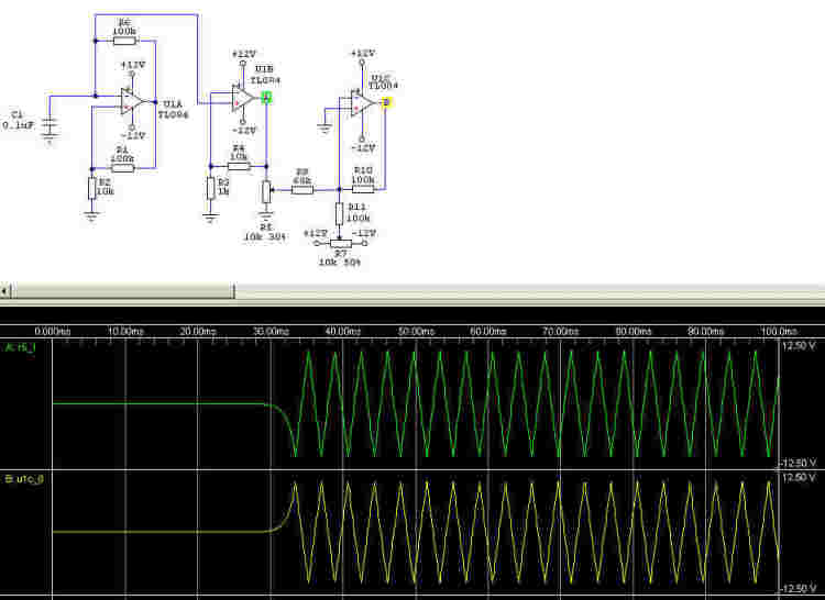
TL084(d), in a log amplifier configuration drive
the Y input of the oscilloscope. The other 3 amps of TL084 (a, b, c) are
used to generate the sweep signal. The output of (b) it will drive the
X input of the oscilloscope.
This design expect to be a cheap Spectrum Analyzer,
but in the same time with nice performances. For more improvements you
can add a step attenuator, more poles to the front end low pass filter,
switchable filters on 10.7MHz IF, a variable BW video amplifier for vertical
output etc.
Iulian Rosu, VA3IUL / YO3DAC
Home http://www.qsl.net/va3iul/
Block Diagram
Sweeper - Spice waveforms