DESIGN CONSTRAINTS The VE6WZ QTH is a small city lot about 100’ X 60’ and this put limits on boom and element length. The tower is offset only 14’ from the eastern neighbor, so the maximum boom length possible was 28’. Using 66’ long elements it was possible to keep the antenna within the VE6WZ "air-space". (when not QRV the crank-up tower is kept retracted at the 30' level). Modeling shows that this close element spacing still achieves acceptable gain and F/B figures. The feedpoint impedance and bandwidth are also manageable. At left is shown the very approximate half-element dimensions. The 40m elements are spaced 22', and the 80m elements have 28' spacing. |
MININEC MODELING NEC4WIN was used to model the yagi. A full size 2 el model was first created to confirm that the short boom design would yield an acceptable pattern. The 40m elements were added to the model, and the 80m elements were shortened to 66’ and loaded with the necessary inductance of about 30 uH to tune them to the required resonance points. A series 1-ohm resistance was included at each coil to approximate the coil loss. Element diameters where selected to closely reflect the final mechanical design of the aluminum tubing used. The reflector element was "tuned" for maximum F/B close to the desired minimum SWR frequency (3795 kHz). Plots of Gain, F/B and SWR vs. frequency were created to analyze the bandwidth of the model. Azimuth and elevation plots were made to analyze the far-field pattern of the antenna at a height of 100’. These plots and patterns are all shown below. |
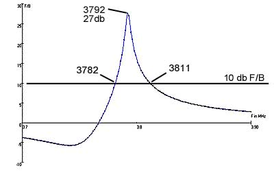
F/B VS. FREQUENCY |
GAIN VS. FREQUENCY |
SWR VS. FREQUENCY AND IMPEDANCE CHART At 3.786 MHz Z = 13.40
- j 11.57 SWR = 2.210 |
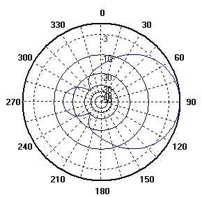
Azimuth Total Field at 3795 |
Zenith Total Field at 3795 |
Azimuth Total Field at 3800 |
Zenith Total Field at 3800 |
|
Azimuth Total Field at 3790 |
Zenith Total Field at 3790 |
|
Azimuth Total Field at 3785 |
Zenith Total Field at 3785 |