When a plug other than the PG-2V or PG-3C is inserted into the DC IN jack, the ground side of the jack may not disconnect. This may cause the external DC power to be supplied directly to the internal battery which results in overheating the battery and blowing the fuse. To protect the battery, replace the fuse with a protection diode, part number ERB83-004.
Note models with serial numbers greater than 801XXXX allready incorporate this diode as D16.
This modification may be performed under warranty.
Time required for this
change is 1/2 hour or less.
19-07-1998 144 - 165 TX/RX mod for the
TH-205
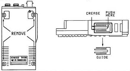
To open your th-205,215,or 225 all you have to do is take
out the screws on the back, and gently open up the front of the
unit...
Locate the obvious 4 jumper bridges on the pc board. The bridges are
numbered j-1, j-2, j-3, and j-4..Jumper j-3 has already been cut...
Carefully
snip jumpers j-1 and j-2 and ever so slightly seperate the snipped bridges to
insure no-contact betwen the points.. Reassemble the unit..Look at your
instruction manual and reset the microprocessor..The mod will not work until you
reset the mpu...
The info. For reset is near the back of the manual..After
that the unit is wide open to operate between 144 to 165.
06-01-2000 Expanding TX and RX for Kenwwod
TH-205
Remove rear cover from handheld, on the board you will see
easily three solder links, bridge the left and the middle links.
Turn the radio back on.
This mod expands the RX more than the
TX.
The transceivers mentioned above can be mechanically improved by adding a bracket assembly to the volume and squelch controls. The bracket assembly is being used in current production and is available for older units from the Kenwood Parts Department.
Bracket Ass'y (W05-0235-00)

This modification may be covered under warranty.
Time required for this
modification is ½ hour or less.
16-04-2000 TH-205 Signal-To-Noise ratio
improvement
Author: Trio-Kenwood
Communication, inc.
During strong signal reception, the noise level may appear to increase due to unstable action of the active filter in the PLL. To improve the sig-to-noise ratio, install a 390 Kohm resistor on the emitter of Q12 (active filter) as described below.
Required parts:
390 Kohm chip resistor (RK73FB2A394J)


This modification may be covered under warranty.
Time required for this
modification is ½ hour or less.
21-04-2000 TH-205/215/315/415 PTT knob
installation procedure
Author:
Kenwood Communication, inc.
The original plastic knob (K29-3054-15) has been replaced with a rubber knob (K29-3054-35). The PTT mounting guide on the front panel must be removed to allow the new knob to be installed. The following procedure will explain the installation procedure.