Modifications for the Kenwood
TH-48
Picture

19-07-1998 Secret function manual of the
KENWOOD TH-28e/48e porto
TH-28e/48e RX EXPANSION
(ON)
Press PTT + VFO, then POWER ON.
New RX ranges TH28e after
this modification:
VHF Band 136 - 174 Mhz (FM)
UHF Band 400 - 520 Mhz
(FM)
TH48e:
UHF Band 400 - 470 Mhz (FM)
VHF Band 136 - 174 Mhz
(FM)
TH28e Air Band Expansion
Press F key for 1 sec. Then
press LOW key.
New RX ranges
108 - 118 Mhz (FM)
118 - 136 Mhz
(AM)
TH28e 340 - 400 Mhz Expansion
Remove the diode D8 from the
control unit. (FM mode only) With Air Band and 340 Mhz expansion, operating band
can be changed:
           _________      _________      __________
     ---->I AMATEUR I====I 340 Mhz I--->I AIR BAND I_____
     I    I_________I    I_________I    I__________I     I
     I___________________________________________________I
TH48e 340 MHZ & 900 MHZ EXPANSION
Remove the diode D8
from the control unit to cover 340 - 400 Mhz and 800 - 950 Mhz FM mode.
           _________      _________      _________
      --->I AMATEUR I--->I 340 Mhz I--->I 900 Mhz I_____
     I    I_________I    I_________I    I_________I     I
     I__________________________________________________I
TH-28e/48e TX EXPANSION
Remove the diode D10 from the
control unit.
New TX ranges after this modification:
TH28e:
VHF
Band 136.000 - 174.250 Mhz (FM)
TH48e:
UHF Band 400.000 - 470.000 Mhz
(FM)
Note:
Manufacturer guarantees TX/RX specification only in amateur
band. The above frequency range is for the microprocessor's range so that the
receiver sensitivity or TX output power of expanded band may be
reduced.
TH-48E TX/RX 432-438 Mhz LIMITED RANGE
Remove the
diode D14 from the control unit.
TH28e/48e CROSS BAND
REPEATER
Remove the diode D4 then press F key for 1 sec. and press 0
key.
TH-28a/e-48a/e FREQUENCY EXTENSION
Open the case and
remove or add the destination chip diode D10, D11, D14 and D15 on the component
side of the control unit.
(X53-340X-XX, X53-341X-XX)
The frequncy can then
be extended as shown in the table 1 an 2 on page 3 and 4.(See the destination
chip diode position drawing on the attached sheet.)
Notes:
The
frequency display range may differ from the PLL lock range.
  ___________________________________________________________________
 I                   I       360-Mhz band    I        Air band       I
 I===================I=======================I=======================I
 I        Step       I5,10,15,20,12.5,25 Khz I5,10,15,20,12.5,25 Khz I
 I-------------------I-----------------------I-----------------------I
 I  Frequency range  I340.000-399.987.5 Mhz  I 100.000 - 117.975 Mhz I
 I                   I          FM           I          FM           I
 I                   I                       I 118.000 - 135.995 Mhz I
 I                   I                       I          AM           I
 I-------------------I-----------------------I-----------------------I
 I Initial frequency I       340.000 Mhz     I      118.000 Mhz      I
 I___________________I_______________________I_______________________I
Initial step value is 12.5 Khz for 360-Mhz band and 25 Khz for Air
band.
TH-48a/e BAND EXTENSION
The 360 Mhz band and the 800 Mhz
band can be received. To expand the 360-Mhz band and the 800-Mhz band remove
chip diode D8 of the control unit as shown in table 2.
You can switch between
the UHF amateur band the 360-Mhz band and the 800-Mhz band by pressing the [ F ]
key for 1 sec. and then the [ LOW ] key.
  ___________________________________________________________________
 I                   I      360-Mhz band     I     800-Mhz band      I
 I===================I=======================I=======================I
 I        Step       I5,10,15,20,12.5,25 Khz I      12.5,25 Khz      I
 I-------------------I-----------------------I-----------------------I
 I  Frequency range  I 340.000-399.987.5 Mhz I 800.000-949.987.5 Mhz I
 I                   I          FM           I          FM           I
 I-------------------I-----------------------I-----------------------I
 I Initial frequency I       340.000 Mhz     I      850.000 Mhz      I
 I___________________I_______________________I_______________________I
Note:
Program scan is not possible over several bands, but is possible
within each band.
Initial step value is 12.5 Khz.
Table 1 TH28a/e
 __________________________________________________________________
I    Destination bit     I    IGuaranteed I  TX (Mhz) I  RX (Mhz) I
I________________________IDestI___________I___________I___________I
I B4 I B3 I B2 I B1 I B0 I    I Min I Max I Min I Max I Min I Max I
I----I----I----I----I----I----I-----I-----I-----I-----I-----I-----I
I  O I  O I  O I  X I  O I E2 I 144 I 146 I 136 I 174 I 136 I 174 I
I----I----I----I----I----I----I-----I-----I-----I-----I-----I-----I
I  O I  O I  O I  X I  X I E2 I 144 I 146 I 136 I 174 I 136 I 174 I
I----I----I----I----I----I----I-----I-----I-----I-----I-----I-----I
I  O I  X I  O I  X I  O I M2 I 144 I 148 I 136 I 174 I 136 I 174 I
I----I----I----I----I----I----I-----I-----I-----I-----I-----I-----I
I  O I  X I  O I  X I  X I M2 I 144 I 148 I 136 I 174 I 136 I 174 I
I----I----I----I----I----I----I-----I-----I-----I-----I-----I-----I
I  X I  O I  O I  X I  O I X2 I 144 I 148 I 136 I 174 I 136 I 174 I
I----I----I----I----I----I----I-----I-----I-----I-----I-----I-----I
I  X I  O I  O I  X I  X I X2 I 144 I 148 I 136 I 174 I 136 I 174 I
I----I----I----I----I----I----I-----I-----I-----I-----I-----I-----I
I  X I  O I  X I  X I  O I K2 I 144 I 148 I 142 I 152 I 136 I 174 I
I----I----I----I----I----I----I-----I-----I-----I-----I-----I-----I
I  X I  O I  X I  X I  X I K2 I 144 I 148 I 142 I 152 I 136 I 174 I
I____I____I____I____I____I____I_____I_____I_____I_____I_____I_____I
 D15  D11  D14  D10  D8                                           :
   O = Jumpered   X = No jumper                                   :
......<............<.............<.............<.............<....:

:                                                       ____________
:                                                      I  Sub-UHF
:______________________________________________________I____________
I Reset I Offset I Shift I Auto I 1750 I  Air  I  360  I RX (Mhz)  I
I freq- I  freq- I freq- I shiftI tone I band  I band  I-----------I
I       I        I       I      I      I       I       I Min I Max I
I-------I--------I-------I------I------I-------I-------I-----I-----I
I  144  I  0.6   I  12.5 I  O   I   O  I   O   I       I 400 I 520 I
I-------I--------I-------I------I------I-------I-------I-----I-----I
I  144  I  0.6   I  12.5 I  O   I   O  I   O   I   O   I 400 I 520 I
I-------I--------I-------I------I------I-------I-------I-----I-----I
I  144  I  0.6   I  12.5 I      I      I   O   I       I 400 I 520 I
I-------I--------I-------I------I------I-------I-------I-----I-----I
I  144  I  0.6   I  12.5 I      I      I   O   I   O   I 400 I 520 I
I-------I--------I-------I------I------I-------I-------I-----I-----I
I  144  I  0.6   I   5   I  O   I      I   O   I       I 400 I 520 I
I-------I--------I-------I------I------I-------I-------I-----I-----I
I  144  I  0.6   I   5   I  O   I      I   O   I   O   I 400 I 520 I
I-------I--------I-------I------I------I-------I-------I-----I-----I
I  144  I  0.6   I   5   I  O   I      I   O   I       I 438 I 450 I
I-------I--------I-------I------I------I-------I-------I-----I-----I
I  144  I  0.6   I   5   I  O   I      I   O   I   O   I 400 I 520 I
I_______I________I_______I______I______I_______I_______I_____I_____I
                                                                   :
                                                                   :
......<............<.............<.............<.............<.....:
:
:______________
    Sub-UHF    I
 ______________I
I Reset I Step I      .......>.....I-------I------I
I freq. I freq.I      :            I  430  I  25  I
I       I      I      :            I-------I------I
I-------I------I      :            I  430  I  25  I
I  430  I  25  I      :            I-------I------I
I-------I------I      :            I  440  I  25  I
I  430  I  25  I      :            I-------I------I
I-------I------I      :            I  440  I  25  I
I  400  I  25  I      :            I_______I______I
I-------I------I      :
I  400  I  25  I      :
I-------I------I....>.:
Table 2 TH48a/e
 __________________________________________________________________
I    Destination bit     I    IGuaranteed I  TX (Mhz) I  RX (Mhz) I
I________________________IDestI___________I___________I___________I
I B4 I B3 I B2 I B1 I B0 I    I Min I Max I Min I Max I Min I Max I
I----I----I----I----I----I----I-----I-----I-----I-----I-----I-----I
I  O I  O I  X I  O I  O I E3 I 430 I 440 I 400 I 470 I 400 I 470 I
I----I----I----I----I----I----I-----I-----I-----I-----I-----I-----I
I  O I  O I  X I  O I  X I E3 I 430 I 440 I 400 I 470 I 400 I 470 I
I----I----I----I----I----I----I-----I-----I-----I-----I-----I-----I
I  O I  X I  O I  X I  O I M2 I 430 I 440 I 400 I 470 I 400 I 470 I
I----I----I----I----I----I----I-----I-----I-----I-----I-----I-----I
I  O I  X I  O I  X I  X I M2 I 430 I 440 I 400 I 470 I 400 I 470 I
I----I----I----I----I----I----I-----I-----I-----I-----I-----I-----I
I  X I  O I  O I  X I  O I X2 I 430 I 440 I 400 I 470 I 400 I 470 I
I----I----I----I----I----I----I-----I-----I-----I-----I-----I-----I
I  X I  O I  O I  X I  X I X2 I 430 I 440 I 400 I 470 I 400 I 470 I
I----I----I----I----I----I----I-----I-----I-----I-----I-----I-----I
I  X I  O I  X I  X I  O I K2 I 438 I 450 I 400 I 470 I 400 I 470 I
I----I----I----I----I----I----I-----I-----I-----I-----I-----I-----I
I  X I  O I  X I  X I  X I K2 I 438 I 450 I 400 I 470 I 400 I 470 I
I____I____I____I____I____I____I_____I_____I_____I_____I_____I_____I
 D15  D11  D14  D10  D8                                           :
   O = Jumpered   X = No jumper                                   :
......<............<.............<.............<.............<....:

:                                                       ____________
:                                                      I  Sub-VHF
:______________________________________________________I____________
I Reset I Offset I Shift I Auto I 1750 I  360  I  800  I RX (Mhz)  I
I freq- I  freq- I freq- I shiftI tone I band  I band  I-----------I
I       I        I       I      I      I       I       I Min I Max I
I-------I--------I-------I------I------I-------I-------I-----I-----I
I  430  I   *    I   25  I      I   O  I       I       I 136 I 174 I
I-------I--------I-------I------I------I-------I-------I-----I-----I
I  430  I   *    I   25  I      I   O  I   O   I   O   I 136 I 174 I
I-------I--------I-------I------I------I-------I-------I-----I-----I
I  430  I   5    I   25  I      I      I       I       I 136 I 174 I
I-------I--------I-------I------I------I-------I-------I-----I-----I
I  430  I   5    I   25  I      I      I   O   I   O   I 136 I 174 I
I-------I--------I-------I------I------I-------I-------I-----I-----I
I  430  I   5    I   25  I      I      I       I       I 136 I 174 I
I-------I--------I-------I------I------I-------I-------I-----I-----I
I  430  I   5    I   25  I      I      I   O   I   O   I 136 I 174 I
I-------I--------I-------I------I------I-------I-------I-----I-----I
I  440  I   5    I   25  I      I      I       I       I 136 I 174 I
I-------I--------I-------I------I------I-------I-------I-----I-----I
I  440  I   5    I   25  I      I      I   O   I   O   I 136 I 174 I
I_______I________I_______I______I______I_______I_______I_____I_____I
         * = 1.6M, -7.6M                                           :
                                                                   :
......<............<.............<.............<.............<.....:
:
:______________
    Sub-UHF    I
 ______________I
I Reset I Step I      .......>.....I-------I------I
I freq. I freq.I      :            I  144  I   5  I
I       I      I      :            I-------I------I
I-------I------I      :            I  144  I   5  I
I  144  I 12.5 I      :            I-------I------I
I-------I------I      :            I  144  I   5  I
I  144  I 12.5 I      :            I-------I------I
I-------I------I      :            I  144  I   5  I
I  136  I 12.5 I      :            I_______I______I
I-------I------I      :
I  136  I 12.5 I      :
I-------I------I....>.:
CLONING BY RADIO
- Overview of the clone function. (The function does not require frequency
expansion.)
Since 240 channels are available if an option is installed, it
is laborious to write the same memory channel frequency data into several
transceivers. Once you write data into one transceiver, you can duplicate it
in several others in a single operation with the clone function. (You can
write data without installing an option.)
- How to use the clone function.
Transmitter setup:
- Write the required memory channel frequency data into the transceiver.
- Set the transmit frequency.
- Switch the power off, hold down the 7 key on an F series tranceiver or
the MR and PTT keys on a K series, and switch the power on again.
"CLONE" appears on the display.
(The transmit output is
automatically set to "economic low".)
Receiver setup:
- Set the frequency of the transceiver to the transmit frequency of the
transmitter.
- Switch the power off, hold down the 7 key on an F series transceiver or
the MR and PTT keys on a K series one, and switch the power on again.
"CLONE" appears on the display.
Press the PTT key on the
transmitter. The clone function works automatically. When cloning ends, the
frequency is displayed again.
It takes about four minutes to transfer
frequency data for 40 channels, and about nine minutes to transfer frequency
data for 240 channels.
If the receiver is an F series one and the frequency
is displayed again, switch the power off, hold down the F key, and switch the
power on again (VFO reset). If the receiver is a K series one and the
frequency is displayed again, switch the power off and on again.
Thus,
cloning lets you copy the channel data stored in the transmitter to other
transceivers in a single operation. To stop cloning, switch the power off and
on again.
 __________________________________
I                                  I
I          Control Unit            I        Bit 0.....D8   (MA110)
I                                  I        Bit 1.....D10  (MA110)
I     TH28a/e : X53-340X-XX        I        Bit 2.....D14  (MA110)
I     TH48a/e : X53-341X-XX        I        Bit 3.....D11  (MA110)
I                                  I        Bit 4.....D15  (MA110)
I                                  I
I                                  I
I                                  I
I                                  I
I                                  I
I   D15     D14                    I
I      \_ _/                       I
I      I I I                       I
I      I_I_I       D10 D8          I
I              _ _/  _/            I
I         D11-I I I I I            I
I             I_I_I I_I            I
I__________________________________I

I                                  I
I          Control Unit            I
I          X53-3420-00 A/5         I
I                                  I
I      .............               I
I      :           :               I
I      :    CPU    :  ___          I
I      :           : I___I D1      I
I      :           : I___I D2      I
I      :...........: I___I D3      I
I                    I___I D4      I
I                    I___I D5      I
I                    I___I D6      I
I                                  I
I__________________________________I
27-03-2000 Extended
UHF TX. Also VHF/UHF/Cellular RX Modification
Author: Colin G1IVG - [email protected]
RX Coverage
After Modification. VHF. 136 MHz to 174 MHz FM
UHF. 340 MHz to 470 MHz FM
Cellular. 800 MHz to 950 MHz FM
(To select the different UHF bands after the modification you must make sure
that you are in UHF VFO mode, then press for two two seconds
and then . This toggles the different UHF bands).
Procedure.
- Remove the battery.
- Remove the four screws on the rear of the radio (not the belt clip
screws).
- To open the radio, I found it best to put your thumb into the battery
compartment and by applying slight pressure on the inside of the rear cover,
with your thumb the radio will open.
- As you open the case, take care not to damage the ribbon cable.
- Put the radio face down on a clean surface with the front of the radio
facing down and to the right. The back of the radio should then be to the left
and on it's back.
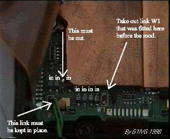
- Look at the photo below for the location of the surface mount
resistors.
- On my radio, originally there were two green link wires fitted to
the PCB. The photo below shows my radio after modification. The wire link to
remove is "W1". However leave link "W2" in place.
- Now you need to configure the small surface mount resistors as shown in
the photo. Just copy the configuration as shown and this will give you the
coverage printed above. Take care when removing the resistors as to much heat
from your soldering iron will lift the PCB track and possibly destroy your
Kenwood TH48. If your not sure then ask an experienced technician to do the
soldering etc.
- Then reassemble the radio, taking care not to trap the existing link wire
"W2" between the two parts of the case. Also take care again of the ribbon
cable.
Layout of surface mount resistors and green link "W2"
After
the modification.
These modifications work 100% on my own Kenwood TH48E, the serial number of
my radio is 60100848. However I can't guarantee they will work on your
particular model. (The serial number can be found inside the battery compartment
of the radio).
23-04-2000 TH-28/48/78 Difficult battery
insertion
Author: Kenwood
Communication, inc.
Service Bulletin no. 1028 (29 June 1993)
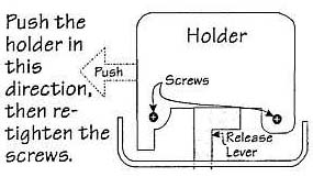
Symptom:
Insertion of the battery into the transceiver is difficult
or impossible due to problems with the release lever.
Corrective Action:
- A temporary cure is provide by loosening the two screws securing the
holder, shifting the holder to the extreme left, then retightening the
screws.
- A permanent fix is provide by replacing the holder and release level with
new parts that have been deburred and modified to allow relocation of the
release level.
Parts required:
Qty   Description                          Kenwood Part No.  Circuit description
 1    Holder                               J19-1515-23       NA
 1    Release lever                        D10-0610-13       NA
Time required for this modification is 30 minutes or less.
23-04-2000 TH-28/48A/E CTCSS tone
error
Author: Kenwood
Communication, inc.
Service Bulletin no. 1037 (18 March 1994)
Symptom:
Several reports were received on early model TH-28/48's
concerning an inability to access sub-audible tone controlled repeaters. This
symptom only occurred when the repeater required the use of any of the following
tones:
Corrective Action:
A microprocessor software error is responsible
for this symptom. Replacing microprocessor IC6 on board X53-3400 (TH-28) or
X53-3410 (TH-48) with the part listed below will correct this symptom.
Parts required:
Qty   Description                Old part No.      New Part No    Circuit desc.
 1    Microprocessor             HD404629A73H      HD404729A79H   IC6
Caution: This modification requires soldering equipment rated for
CMOS type circuits. It also requires familiarity with surface mount soldering
techniques. If you do not have the proper equipment or knowledge do not attempt
this modification yourself. Seek qualified assistance.
Time required for this modification is 30 minutes or less.
23-04-2000 TH-48A Microprocessor
change
Author: Kenwood
Communication, inc.
Service Bulletin no. 1039 (10 February 1994)
Symptom:
Due to a recent rule change by the FCC it is no longer
possible to supply transceivers, or provide replacement microprocessor that
would allow a transceiver to receive in the 800 MHz band.
Corrective action:
The microprocessor program of IC5 has been
modified to prevent 800 MHz band reception. Production has been changed
beginning with serial number lot 510xxxx. Units produced after this point will
not be capable of 800 MHz reception.
Parts required:
Qty   Description                Old part No.      New Part No
 1    Microprocessor             HD404629A79H      HD404629B44H
Procedure:
When ordering a replacement microprocessor you will be
supplied with the new version. Please make sure your customer understands the
limitations of this new