Modifications for the Kenwood
TH-78

19-07-1998 Basics of modifying the Kenwood
TH-78a
To open the radio, follow the instructions on page 64 of
the manual.
(Unscrew four screws and break apart the radio halves.) The two
TX/RX busy indicators (LEDs) have rubber seals placed over them. These have a
tendency to fall off when opening or closing the radio.
All position
references in this document assume that you are looking at the CPU board with
the rotary encoders and TX/RX busy indicators at the top.
If you have
installed the ME-1 EEPROM, I recommend that you temporarily remove it to
facilitate access to the diodes.
You'll see a brass shield about one
centimeter square covering the processor chip and the surface-mount diodes on
the back half of the radio.
De-solder the shield's four corners and remove
it. (I used an right angle surgical tweezers in conjunction with the pin-point
soldering iron to lift the brass shield.)
Uncovered are the processor
(which we ignore) and six surface-mount diodes, numbered sequentially from one
through six (D1 - D6), top to bottom. These are about one millimeter wide;
remember the note about skill and finesse.
New model radios also have two
large loops of green wire, numbered one through two (W1 - W2), bottom to
top.
You'll need a pinpoint-tip soldering iron and some braid to wick
away the solder before you lift out the diode. Alternatively, Rich Garcia
([email protected]) suggests leaving the diode in place. "I found if you BRIEFLY
touch the iron to the right side lead while gently pulling up on the SMC diode
it should completely come off without needing to apply heat to the other side
and further risk board damage."
After you perform some or all of the mods
listed below, replace the brass shield and re-assemble the radio. Then reset the
processor (as documented) and re-enter any frequencies into
memory.
19-07-1998 Potential
case design flaw
From [email protected] (which no longer
exists):
In the course of performing mods on my Kenwood TH-78a dual
band handheld, I've discovered a potential flaw in the case design. While
handling my walkie one day (after the mods were done), the display went blank
and I could not turn the radio back on. With the radio split in half again, I
could turn the radio back on but discovered all the memories were erased. The
cause turned out to be some component pins on the front face coming in contact
with the square bodies of the two volume/channel/squelch switches, when the case
is screwed back together snuggly. I placed small strips of electrical tape on
the sides of the switches to insulate, and reassembled; problem solved. Now I
have to reprogram the darn thing....
[email protected] (Mark
Olson) said:
There is a warning on some of the rig mod bulletin
boards about this. The problem is that pins on the back side of the PCB that is
mounted on the front half of the TH78 can come into contact with the volume
control housings mounted on the PCB on the other half of the unit. My radio had
this problem until I put electrical tape across these housings. Symptoms were:
Display blanking momentarily and the unit power cycling, sometimes causing
memory erase, when pressure was applied to the front of the unit or to the
volume controls. I originally thought that it was a loose battery
connection...
Open up the radio and you will see what I mean... Believe
me, the fix is simple and it works.
19-07-1998 C-17 design
flaw
[email protected]
said:
"The 78A WILL lose C-17 on the control board if dropped,
period. This causes loss on receive audio on the left-hand side of the radio.
The solder pads for that cap are not big enough. If you find the need to replace
C-17, use a gap-fill cyanoacrylate glue like Zap-A-Gap (tm) to increase the
device footprint. I have learned the hard way.
Otherwise, I have found it to
be a fine radio. My only problems have been related to the C-17 issue and
attempts to rectify it. Had I been given the above advice, it would have been a
one-time only issue. As it is, I took out one of the microprocessors yesterday
looking for a bad solder joint that was induced by my attempt to solve the C-17
problem (sigh). This radio gets a lot of use and a lot of travel. C-17 is the
only thing that I have broken with the case closed.
19-07-1998 Mutually exclusive
mods
Some of these mods are reputed to be mutually exclusive. You
must choose one of the following levels of performance:
The "beyond MARS"
mod - gets you the widest tx/rx
The "MARS/CAPS" mod - halfway there
The
"extended receive" mod - more of a good thing
plus
The "cross-band
repeat" mod - a repeater that weighs almost nothing
There is no mods that
manipulate diodes D1 or D2 (I've seen it suggested elsewhere that this is
toggles the USA/Europe-ness).
[email protected]
suggests:
"I think removal of D1 causes "Forced Channelized Mode", at
least on the "new" radios. If you put both VHF and UHF memories into a TH78A
without D1 and power on, you are stuck in channel mode until you do a full
memory reset. Remember, you can't add frequencies or do any tuning in channel
mode.
If you think about it, you'll want to be very careful not to let
D1's circut become an open circut.
19-07-1998 The beyond MARS
mod
This mod provides the widest possible range of tx/rx. The
mother of all TH-78a mods.
To mod (early model): remove diode D5
only.
To mod (late model): remove diode D3 and cut wire W1. D5 has
priority over D3, so if you've already made the mods for the old model (which
included the removal of D5) you must resolder D3 into D5.
Yields RX
50-179.995, TX 136-179.995, RX 300-399.995, RX 400-511.995, TX 400-511.995, RX
800-999.995.
To use: buttons operate the same way as described in the
"extended receive" mod, except that you can transmit on a much wider
range.
NOTE TO ALL: I haven't been able to verify the actual operation of
my radio on all these freqs. Kenwood talks about the difference between the
"dialable" range and the operating range. I'd like to come up with a chart for
each level of mod that combines the above and the two following offerings. Help
me, please.
* * * * * * * * * * * * * * * * * * * * * * * * * * * *

        Left VFO                        Right VFO
50.000-85.2x (with beep)                50.000-110.xxx (with beep)
85.2x-179.995                   110.xxx-179.995
300.00-399.975
400.000-511.9875                400.000-511.9875
                                800.00-999.9875

* * * * * * * * * * * * * * * * * * * * * * * * * * * *

Receive                         Transmit
---------------                 ---------------
50-135.995 (AM)        VHF      (NA)
136-179.995             "       136-179.995
300-399 (AM & FM)       "       (NA)
400-511.99           SUB-UHF    400-511.99

400-511.99             UHF      400-511.99
900-949.9875            "       (NA)
50-179.995 (FM)      SUB-VHF    136-179.995
19-07-1998 The
CAP/MARS mod
This doesn't cover as much room as the beyond MARS
mod does, but may be more appropriate for those who use the CAP or MARS
frequencies.
To mod (both early and late models): remove D6
only.
Yields RX 118-173.995, TX 142-151.995, RX 400-511.995, TX
425-454.995.
19-07-1998 The extended receive
mod
This is the mod that's usually given to hams to pacify them
(the beyond MARS mod is closely guarded).
To mod (both early and late
models): remove diode D5.
To use: press "F" for one second and then
pressing the Band button will switch the UHF VFO to a 800-999.995 MHz band and
the VHF VFO to a 300-399.995 MHz band. The regular VHF VFO can now receive down
to 50 Mhz.
19-07-1998 The cross-band repeat
mod
To mod: remove diode D4.
To use: press "F" for one
second, then "0". Repeat to disable. The MHz dot will flash when in repeater
mode.
19-07-1998 Toggle
SHIFT button function
Press SHIFT during power-up This is
described in the manual, but the documentation is not complete. The TH-78A can
operate in two modes: In SPLIT mode, non-standard offsets (i.e. split
frequencies) are supported, but the default offset is not programmable. In SHIFT
mode, non-standard offsets are not allowed, but the default offset is
programmable. To select the default offset, press F for 1 second, then SHIFT.
See p. 30 of the manual for details on changing the default
offset.
19-07-1998 Toggle CALL
button function
Press CALL during power-up. The CALL button can
operate in one of two modes. In the default mode (CALLSW), it switches between
the call channel and the last memory channel (if in memory recall mode) or last
frequency (if in VFO mode).
After toggling the CALL button functionality
(VMC), it will switch from the VFO to the last memory channel and then back to
the CALL channel.
19-07-1998 Observations on post-mod
performance
Rich Garcia ([email protected]) observes "all
original functions have maintained the same which is great. Aircraft band which
was accessible before the mod remains with the same characteristics. It seems
that VHF-High band has improved a bit on sensivity where it was dead as a dog
before the mod (above 155.000MHz) but the 162.000 MHz band where weather radio
is is still a bit deaf for reception at any distance but about 20 Miles. This
depends on your (or my) terrain and transmitter output power.
"On UHF all
public safety frequencies up to about 500 MHz seem to come in well but sensivity
greatly drops from there (we really can't ask for more).
Frequencies can be
programed in up to the 920MHz ham band but I have no way of measuring sensivity.
800MHz works but the signals are very weak, you must be near the transmitter for
reception. Assuming you are in the town or city where the transmissions
originate it should work.
"Transmit is enabled up to and incl. 500MHz but
after testing this on a frequency counter I find that a signal is only generated
to about 490 MHz, even though the trans. LED shows output in the higher
frequencies.
"Crossband repeat seems to work fine but the audio is
unacceptable for use, BE AWARE the radio gets HOT! Prolonged use or use on a
busy frequency would not be recommended. Also remember this is a dual band HT
please use a proper antenna while in this mode to avoid a high SWR, we should
all know better... Right?"
Someone else said:
"I found that marine
weather reports at 162.40MHz in my area were received much better on the SUB-VHF
band, than on the VHF band...
"If you are having problems with intermod,
try switching bands (i.e. using the SUB-VHF band rather than the VHF
band.)"
19-07-1998
Cloning
The TH-78a's memory can be copied from one TH-78a to
another TH-78a entirely through radio waves "over the air" (i.e. without cables
or other special equipment). Theoretically, this could be done via repeaters,
although I've never heard it done. Allegedly this requires a mod that includes
removal of D5 or D6, but I haven't researched it.
Cloning is a real boon
to groups that want a bunch of radios to contain the same memories, such as
amateur radio clubs, search and rescue units, and people too lazy to program
their radios. Of course, given that the ME-1 memory expansion unit has 250
memories, laziness is understandable :-)
- Set both radios to the same frequency.
- Activate both radios by pressing the '0' key while turning the power on.
The radios will display the word "clone".
- Now, click the PTT button of the "master" radio. The radio will transmit
in the economy low power mode. This may take about 4 minutes for fifty
channels, or 20 minutes for the 250-memory ME-1. When the data has been
transferred, both radios will revert back to their original frequency.
(It
is recommended that a dummy load be used to prevent unwanted interference.)
- Turn both radios off and then on again. The slave is now a mirror-image of
the master radio.
19-07-1998 Cellular
Telephones
Cellular phones operate at (tx) 824.040 - 848.970 (rx)
869.040 - 893.970, within reach of your modified TH-78a. The increments are,
however, every 30kHz; the TH-78a will only increment in 25kHz steps at this
frequency range, so the exact cellular frequency cannot be tuned in (most of the
time).
19-07-1998 Battery
life on the TH-78A
[email protected] (Eric Williams)
says:
Some people have complained about the battery life on the
TH-78A. I came up with these tips by checking out the power consumption under
various configurations. In the case of power-saver mode, figuring out the
average current with my DVM was impossible, so I ran the radio on a large
capacitor and timed how long it took to die. These tips won't solve everything,
but they might help.
The rig draws close to 2ma even with the power
turned off, so don't leave the rig off with the battery installed for several
days and expect full capacity to be maintained.
If you're only using one
of the bands, shut down the other to extend your battery's life -- current
consumption with the squelch closed is cut by almost a third.
If you're
monitoring two frequencies on the same band, use the f2 button to receive both
simultaneously rather than scanning between them -- the battery saver with two
receivers will use about half the current of one receiver that is
scanning.
You can make up a battery pack by putting nickel metal hydride
AA cells in a BT-8 battery holder. A small strip of aluminum from the positive
battery terminal to the depression in the top of the case will allow you to
recharge the pack inside the rig. This will give you 1000mah capacity without
enlarging the size of the radio, and NiMH cells have no memory effect. (But they
*are* expensive.)
19-07-1998 Game
Mode
[email protected] (who no longer exists), who
credits
[email protected] for "much of this".
To enter the game
mode press M and PTT during power-up. Be careful not to accidentally reset the
memory, which happens with M + power-up. (Don't freak; you'll see the same "all
screen items lit" when entering game mode as when you reset memory.) To exit the
game mode at any time, press the LAMP key. The volume, lamp, or frequency
settings can't be changed while in game mode.
The top part of the display
will show "H.00", which represents the high score. The lower part shows a
scrolling message, "PRESS ANY KEY". Pushing any key starts a "Follow Simon" type
game. The display will briefly show one of the characters '1', '2', '3', or 'F'.
Press the corresponding key. The game consists of repeating the displayed
character sequence, which increases by one character each round.
After
you "win" the Simon memory game by getting correctly entering a sequence of
twenty characters, the next game is a draw poker game.
The way it works
is that you choose your bet (from 1 to 10) by pressing '2' to increment the bet
and '5' to decrement the bet. Then, press 'F' to deal the five cards. The face
value of the cards is displayed, and the suits can be seen at any time by
holding down the PTT key. Any number of cards may be discarded, and to select
(or deselect) a card for discarding, press the keys '1', '2', '3', '4', or '5'.
If a card is selected for discard, it is displayed "face-down".
Press 'F'
again to draw new cards. Your new cards will be displayed, and then if your hand
is 2-pair or better, the screen will show the rank of your hand on the left (2P
for 2-pair, 4K for four-of-a-kind, etc.). On the right the pay-off for that hand
will be displayed. Your bet is multiplied by the pay-off factor,and the
resulting pile of cash is displayed in the right hand side of the upper screen.
(The left-hand side of the upper screen contains your table stakes, which are
initially 100 coins from winning the Simon game.)
If you win the poker
hand, pressing any key steps into the next stage. If you lose the poker hand,
your bet is deducted from your stakes and you are asked to start another poker
hand. In the next stage, you are asked "TRYB/S" which means, "Do you want to try
double-or-nothing in a guessing game for Big or Small cards?" Press 'F' for yes,
press TONE for no. If you say no, your winnings are credited into your stakes
and you are asked to start another poker hand. If you say yes, then a single
shuffling/incrementing card is displayed on the left, and three stars are
displayed on the right. You have to choose to go for either BIG or SMALL, by
pressing '2' or '5'. You can keep pressing '2' and '5' to change your mind. When
you are ready, you must try to hit the 'F' key to stop the rotating card
display, and the card will show, and you will either win, lose, or draw. If you
draw, you have to play big/small again, I think. If you lose, your winnings are
gone and you can play poker again. If you win, your winnings double and you are
asked whether you want to play big/small again.
The payoffs on the poker
are set against you, odds-wise; the double-or-nothing game includes a draw, so
the odds are against the player there unless you can time hitting the 'F' key to
win more than half the rounds. I haven't managed to do this, so I don't know if
there is anything beyond this, all I know is that when the table stakes are
exhausted, you go back to playing Simon again.
19-07-1998 TH-78 - antenna
hints
Hello everybody! Recently I decided to check the
performances of small "Duckie" antenna specified as T90-0444-XX in TH78
manual.
I found that on 2 mtrs band this antenna, at first, has quite narrow
bandwidth and, at second, tuned about 144.000 MHz or even some lower ( at the
same time 70cm bandwidth seems to be enough...).
Because of "integrated
design" of this antenna it would be nonsence to cut the top end, so I tried to
find another way to tune it to the middle of 2m band. At last, the problem has
been successfully solved! So, you can easy tune the central frequency up to 147
MHz - just place a copper ring in the middle of conical surface of antenna (
between "OO"s as shown below ):
  +---------------Ê---
  ¦--  ¦          ¦     +-----------------------------+
  ¦--  ¦ K E N W O¦O D   ¦ dual band antenna           ¦)
  ¦--  ¦          ¦     /+-----------------------------+
  +---------------ð---/

               copper ring (about 13 mm internal diameter)
The ring made of 0.3 mm wire gave me frequency shift from 144 to 145 MHz;
if you need higher frequency, you should use wider ring ( about 4...5 mm for 147
MHz ) - you can solder it of thin copper.
Don't use SWR meter for tuning! The
best device is scanning scope or, at least, simplest RF field meter and your HT
as VHF generator.
That's all... 73, de Serge.
RK3AXJ @RK3KP.MSK.RUS.EU
28-Aug-94
19-07-1998 9600 Baud FSK-Modifikation für das
Kenwood TH-78E
From: DG1SFJ @
DB0RBS.#BW.DEU.EU
Hallo Kenwood-Freunde,
hier bekommt Ihr nun
die Anleitung zum Modifizieren eures TH-78's, um damit 9k6 zu machen...
Ich
übernehme keine Verantwortung für die Richtigkeit der in der Anleitung gemachten
Angaben und für Schäden die im und am Gerät durch die Modifikation entstehen.
Die Anleitung ist etwas größer geworden, dafür aber (hoffe ich) einfacher und
auch für Nicht-Profis (etwas Löterfahrung braucht man schon!!)
verständlich.
1. Öffnen des Gerätes:
Alle Stecker incl.
Antennenkabel abziehen, die beiden Drehknöpfe und danach die Squelch-Regler
abziehen. Den Akku entfernen und mit einer halboffenen Schere oder Zange die
beiden Kranz-Muttern an den Squelch-Reglern rausdrehen. Jetzt fällt der obere
Gehäusedeckel ab, aber auf die beiden Gummiringe auf den LED's achten, sie
fallen leicht runter...
Auf der Rückseite des Gerätes die 3 Schrauben
lösen, ebenso wie die kleine Schraube an der Seite beim Antennenanschluß.
Vorsichtig das Gehäuse öffnen. Nun die Hälfte mit der LCD-Anzeige nach links
legen, und die andere nach rechts (wer hätte dies gedacht :-)
An der Platine
mit den Akkukontakten die zwei kleinen Schrauben unten rechts und links
losschrauben, und das Kabel davon abziehen. Diese Platine könnt ihr nun zur
Seite legen, und das CTCSS-Modul sollte, falls vorhanden nun dem Gerät sanft
entnommen werden.
Jetzt nur noch die drei Schrauben auf der Platine
lösen, auf der die Squelch-Regler sitzen. Dann das geschirmte Kabel, das
ebenfalls auf der Platine sitzt und nachher durch ein Loch in dieser
verschwindet, aus der Buchse rausziehen. Nun die gesamte Platine und die
Gehäusehälfte(LCD) nach rechts legen, und auf das kleine Kabel von eben und auf
das Flachbandkabel aufpassen...
Damit liegt die Rückseite der Platine mit
den Squelchreglern vor euch bereit für die Modifikation (letzte Möglichkeit zum
Aufgeben des ganzen Vorhabens ;-)
2. RX-Modifikation:
Auf
dieser vorher genannten Platinenseite befinden sich nun 2 Empfänger-IC's des
Typs MC3372D, je einer für VHF und UHF. Auf dem Schaltplan befinden wir uns nun
auf der (X57-409X-XX B/4) TR-RX Unit, wobei das UHF-IC dort IC303 heißt. Dort
greift ihr das Diskriminator-Signal von Pin 9 ab. Um nun den richtigen IC auf
der Platine mit dem Lötkolben zu traktiern, legt ihr diese wie folgt vor
euch:
Die Squelch-Regler zeigen nach rechts, ein Flachbandkabel geht von
oben zur Druckguß-Schalenhälfte des Gehäuses. Nach unten geht das andere
Flachbandkabel Richtung LCD-Gehäuseteil. Das UHF-Empfänger IC liegt nun weiter
rechts, nahe einem IC mit der Aufschrift "4560 246" in der Nähe der
Squelch-Regler. Wenn ihr diese habt, so lötet ihr nun ein Kabel an Pin 9 an den
MC3372D (in diesem Fall oben rechts das letzte Pin). Es gelten die üblichen Tips
für SMD-Löten (vorher noch mal üben!). Das Kabel nun um ca. 90 Grad nach rechts
biegen, Richtung Squelch-Regler. (solltet ihr es Richtung Akku biegen, und da
auch langführen, dann bekommt ihr ein übles Rauschen auf dem gesamten UHF-Band
und die Squelch läßt sich nicht mehr schließen...). Abgeschirmtes Kabel ist also
anzuraten, ich habe keines verwendet, allerdings unter Beachtung der Richtung
des Kabels wie oben beschrieben.
Damit ist der Demodulator-Ausgang vom
UHF-Empfänger IC schon mal nach aussen gelegt und ihr seid (hoffentlich) bereit
für das Abgreifen der TX-MOD vom Flachbandkabel.
3.
TX-Modifikation:
Dieser Teil der "Modifikation" ist eigentlich auch
kein Problem, man sollte nur ruhige Hände und scharfe Augen haben...
Der
Umbau spielt sich wieder in der (X57-409X-XX B/4) TR-RX UNIT ab, wobei die uns
interessierende Leitung vom Mikrofonverstärker (IC 301) über ein Poti (VR302)
zum Flachbandkabel links auf dem Schaltplan geht, welches dort mit B bezeichnet
wird. Das Signal liegt von unten aus gezählt an Leitung 11 (MODU) an. Wenn die
Platine genauso wie vorher vor euch liegt, so seht ihr oben ein Flachbandkabel
aus Plastik, das in die Gehäusehälfte geht, die mit einer Druckgußhaube
abgedeckt ist (genau die mit dem Antennenanschluß), und rechts wieder die
Drehregler.
An diesem Flachband-Kabel werden nun von links nach rechts
genau 11 in Worten ELF Leitungen abgezählt. Es sieht so aus, als ob keine
Leiterbahn von da aus weiterführt, da die Platine aber innen noch eine Schicht
hat, kann man das jetzt noch nicht erkennen. Um die Zählrichtung noch mal zu
verdeutlichen: Rechts die Squelch-Regler, links gar nichts, und von links aus
die Leitungen des Flachbandkabels abzählen 1,2,3,...,11 und an dieser Leitung
liegt die Modulation für den VCO. Also genau hier, wo das Flachbandkabel an der
Platine festgelötet ist, wird nun ein Kabel angelötet, aber aufpassen:Erstens
hält so ein Kunststoff-Flachbandkabel nicht viel Löterei aus und zweitens ist
schnell mal eine danebenliegende Leitung auf der Platine mitangelötet (ist mir
beinahe passiert...). Das Kabel nun wie vorher auf dem kürzesten Wege nach oben
zu den Squelchreglern legen.
4. Letzte Schritte:
So, die
typischen 2 Drähte sind angelötet, ist auch keine Brücke unerwünscht entstanden
?! OK, dann das ganze Gerät in umgekehrter Reihen-folge wie beim Zerlegen unter
Punkt 1 wieder zusammenbauen, kurzer Funktionstest, und dann kann das ganze
schon an das FSK-Modem angeschlossen werden. Im TNC-Handbuch sollte man nun
nachlesen, wie die Modulation am besten einzustellen ist (ich habe das mit einem
zweiten Empfänger getan).
Gedanken muß man sich nur noch über die
Verbindung zur Aussenwelt machen, entweder einen kleinen Platinensteckverbinder
(3-polig und einen Pol davon abfeilen) oder eine 2,5mm Monobuchse (paßt
wahrscheinlich ebenso nur ab- gefeilt rein) in den Platz (von oben auf die Funke
gesehen) zwischen Antenne und erstem Drehknopf, weil hier der einzige "große"
Platz ist. Bei mir hängen zur Zeit einfach die beiden Kabel oben heraus. Wer
eine bessere Lösung hat, sollte mir diese unbedingt schreiben !
5.
Ergebnis:
Angeschlossen habe ich mein TH78E an einen TNC 2 H, auf den
sich das nun folgende Ergebnis bezieht:
Die TXDELAY arbeitet mit 10
einwandfrei bei mir, mit 9 wird es etwas weniger gut, und 8 war bei mir die
untere Grenze. Weniger ging absolut nicht, und ich nehme zur Zeit 10 oder
9.
Die Filter am TNC habe ich noch nicht mit einem Bit-Error-Test
geprüft, wenn ihr sowas mal macht würde ich mich freuen, wenn ihr mir die
Ergebnisse per PR an meine Box DB0RBS schicken könntet.
Das TH-78 ist
bestimmt nicht ideal für FSK, aber wenn es wie bei mir das einzige 9K6-fähige
Gerät ist, so geht das glaub ich schon. Das ganze habe ich so seit einem Monat
in Betrieb, und es scheint dem Funkgerät nicht zu schaden. Dankeschön noch an
Andre, DG3SDK, der mir beim Umbau geholfen hat !
So, und nun viel Spaß
mit 9600 Baud PR !
Wenn ihr euren Funk auch mal umgebaut habt, dann
schreibt mir doch mal, damit ich seh, wie es bei euch so geklappt hat ... ihr
dürft mir natürlich auch schreiben, wenn es noch Fragen oder Probleme gibt
!
Ansonsten 73 und 55 von Jochen, QTH Schwieberdingen, DG1SFJ @
DB0RBS
19-07-1998 TH78A, USA
model don't have 1750 Hz
TH-78A (U.S.A. version) --> TH78E
(European version) MODS.
If you bought a TH78A in the USA you don't have
the 1750 Hz repeater tone access, but you can change that !
Apart from
the well-known six diodes, the new CPU has 2 green wires.
In order to use
the TH78A in EU, you must do the following:
- First you have to remove D2 for the standard EU bands (144-146 and 430-440
MHz).
- Now control that the 2 green wires and the 5 other diodes are installed
(D1, D3, D4, D5 and D6).
- If you need band expantion and components location, please see the mods
below.
Although the TH78A has a special bandpass filter for the US
70cm band, I could not notice a decrease in sensitivity in the EU part of the 70
cm band.
There is a function change for 3 knobs; please see below and
also p. 6 and 7 of your INSTRUCTION MANUAL.
    TH-78A   -->   TH-78E
    ---------------------------
    LAMP     -->   TONE 1750 Hz
    CALL     -->   LAMP
    TONE     -->   CALL
Now, you can choice between the CTCSS tones and the 1750 Hz with the
following sequence: F + LAMP (the new TONE !) and then the right rotary encoder
to make your frequency choice.
23-01-1999 Crossband repeat, extended
RX/TX
Owner assumes all responsibility for modifying or using
these modifications!.
The following mods will provide for Crossband
Repeat and extended receive and transmit on the Kenwood TH-78A HT.
I
believe other functions are also enabled by these mods. which I have not found
yet but I will update the file as news progresses.
Diode #4- Crossband
Repeat
Diode #5- Extended Receive and out of band Transmit.
Remove all
screws and open radio as explained in the Kenwood manual for installing the
memory expansion module.
On the back cover you will find the memory expansion
module socket and a copper shield to the upper left corner of it.
Under this
shield their will be a row of SMC diodes which are unmarked in a vertical
configuration to the lower right portion covered by the shield.
- Remove the shield at its four corners with a solder sucker and SMALL!
iron.
- Carefully count down from the 1st diode in the row to the fourth one and
remove for crossband repeat.
HINT: I found if you BRIEFLY touch the iron to
the right side lead while gently pulling up on the SMC diode it should
completely come off without needing to apply heat to the other side and
further risk board damage.
I used a pair of right angle surgical tweezers
for this.
- Just as above you may remove the fifth diode to preform the extended
receive and transmit modification.
- Reset the CPU (yes you will loose all of your programed memories! argh!)
by pressing Function for more than one second and then "0".
YOU HAVE NOW
COMPLETED THE MODIFICATIONS!
- For 800Mhz go to the UHF band with the band switch and press Function for
more than one second quickly following with a press of the Band switch again.
8---.-- will appear.
- For 300MHz go to the VHF band and repeat as above. Original bands are
restored by repeating the "F Band" sequence.
MY observations... All
original functions have maintained the same which is great. Aircraft band which
was accessible before the mod remains with the same characteristics. It seems
that VHF-High band has improved a bit on sensivity where it was dead as a dog
before the mod (above 155.000MHz) but the 162.000 MHz band where weather radio
is is still a bit deaf for reception at any distance but about 20 Miles. This
depends on your (or my) terrain and transmitter output power.
On UHF all
public safety frequencies up to about 500 MHz seem to come in well but sensivity
greatly drops from there (we really can't ask for more). Frequencies can be
programed in up to the 920MHz ham band but I have no way of measuring sensivity.
800MHz works but the signals are very weak, you must be near the transmitter for
reception. Assuming you are in the town or city where the transmissions
originate it should work.
Transmit is enabled up to and incl. 500MHz but
after testing this on a frequency counter I find that a signal is only generated
to about 490 MHz, even though the trans. LED shows output in the higher
frequencies.
Crossband repeat seems to work fine but the audio is
unacceptable for use, BE AWARE the radio gets HOT! Prolonged use or use on a
busy frequency would not be recommended. Also remember this is a dual band HT
please use a proper antenna while in this mode to avoid a high SWR, we should
all know better... Right?
After first booting up the CPU in the mod I
found that the message screen showed "Cloning" so it seems that this radio now
has cloning capabilities. After searching I have found that holding the "0" key
and powering up the radio will display the clone feature, see below for further
explination.This leads me to believe that this HT may have some more "Hidden"
features that I am trying to find, some may be useful.
Thanks to Gary
KC8UD who sent me the following via packet .....
CLONING:
The
TH-78 can be cloned without cloning cables or special equipment. It is done
entirely with RF, and, in fact, can be transmitted over the air, and even via
repeaters. This may be extremely useful for those users who do not have the
patience to program their own radios themselves. This application would also be
useful for clubs and user groups. (However, this can take as long as 50 minutes
with the ME-1 expansion module. It is recommended that a dummy load be used to
prevent unwanted QRM.)
- Both radios must be on the same frequency.
- Activate both radios by pressing the "0" key while turning the power on.
The radios will display CLONE.
- Now, click the PTT of the "master" radio. The radio will transmit in the
conomy low power mode. This may take about 4 minutes for fifty
channels.
hen the data has been transferred, both radios will revert back
to the riginal frequency.
- Turn both radios off and then on again. They will now operate normaly
while the slave radio has the same memory contents as the master radio.
FREQUENCY EXPANSION
(1) You can receive from 340 -
399.987 Mhz FM by removing chip diode D8 on the ontrol unit. To access this
function, press the [F] key for one second, and then the [LOW] key. This toggles
between AMATEUR, AIR band (AM) and 360 Mhz.
AM and FM modes are selected
automatically, depending on frequency.
** Since "F" for a second and
"Low" toggles the power output, I wonder **
There is also a couple of
arcade type games on the TH-78A. To start the game you pres and hold [PTT] and
[M] keys while turning the unit on. The first game is a follow me type game. The
radio beeps and shows a sequence of numbers flashing on the screen. You have to
match the same sequence on the tone pad. Each time the sequence gets longer by
one number. You have to keep remembering the sequence as one gets added each
time. Once you get to a certain high score on that game, it breaks into a poker
type game. To exit the game mode press the LAMP key at any time. The receiver
still works in the game mode and you can adjust volume but no other
features.
RG> The games seem to work fine and it is interesting that
they have inserted that into the programing of the chips. Does anyone know of
any further features in the radio be it games or radio functions.
21-04-2000 TH-78A
Clone failure w/ME-1 installed
Author: Kenwood Communication, inc.
Service Bulletin no. 997 (3 August 1992)
Some TH-78A owners have reported a failure of the cloning feature after the
ME-1 Memory expansion unit is installed. The following modification will correct
this problem.
Note: Since the Cloning feature is not one that is mentioned in the
operators manual, and is basically an unsupported feature, we do not anticipate
many reports of this symptom.
Warning: This radio uses micro-sized surface mount component, and/or
multi-layer circuit boards. If you are not familiar with the techniques for
service of this type of equipment do not attempt this modification yourself.
You will invalidate your warranty if you attempt to modify the equipment and
damage the radio. If you are at all in doubt about your qualification to perform
this modification you should seek qualified assistance.
Required parts:
IC-7 Microprocessor, (HD404629A32H)
Procedure:
- Remove the battery, and antenna.
- Remove the 3 small black #0 phillips head screws from the rear panel of
the transceiver and the 1 small black #0 phillips head screw from the side of
the transceiver near the antenna connector.
- Carefully separate the front panel from the rear of the transceiver and
fold it over to allow access to the rear of the front panel.
- Unsolder the brass shield from the circuit board (4 solder
points).
- Locate IC7 the largest of the two IC's under the shield, unsolder and
remove.
- Install the replacement part. Make sure there are no solder bridges or
cold solder connections.
- Reverse steps 1 - 4 to reassemble.
- Press and hold the "M" key on the front panel, turn on the power, then
release the "M" key to reset the microprocessor.
This modification may be covered under warranty.
Time required for this
modification is 1 hour or less.
22-04-2000 TH-78A Call channel tone
frequency error (Revised)
Author: Kenwood Communication, inc.
Service Bulletin no. 1008 (27 May 1993)
Symptom:
When the TSU-7 CTCSS unit is installed the tone frequency
of the CALL CH is overwritten under the following circumstances:
- Program the Call Channel with a tone between 67.0 Hz and 114.8 Hz. For
example: 100.0 Hz.
- Program any memory channel with any frequency and tone frequency. For
example: 118.8 Hz.
- Recall the memory channel to the VFO.
- Recall the CALL channel. The tone frequency of the call channel changes to
that of the memory channel. (Changes from the programmed 100.0 Hz in the
example to 118.8 Hz).
Parts required:
IC-5, Original part 75517GF-155-3B9, change to:
75517GF-170-3B9
Procedure:
This symptom is caused by a microprocessor programming
error. The cure is to replace the microprocessor (Control Unit X53-3420-00,
IC-5) with the replacement part.
Note: Units with serial numbers 404xxxxx - 406xxxxx have a limited
production microprocessor installed. This microprocessor incorporates the
correction for this error. The part is labeled 75P518GF-JDF3. You do not need to
replace this IC. Units with serial number 407xxx and after will have the
75517GF-170-3B9 microprocessor installed at the factory.
Caution: This modification requires soldering equipment rated for
CMOS type circuits. It also requires familiarity with surface mount soldering
techniques. If you do not have the proper equipment or knowledge do not
attempt this modification yourself. Seek qualified assistance.
Time required for this modification is 1 hour or less.
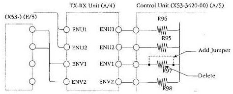
22-04-2000 TH-78A/E Left encoder
inoperative
Author: Kenwood
Communication, inc.
Service Bulletin no. 1013 (7 May 1993)
Symptom:
The left encoder on the top panel does not work. This
symptom usually occurs when the unit is reassembled after service.
Cause:
If the front panel is removed without removing the top panel
the Control unit might come in contact with the encoder mounting hardware. This
causes chip resistor R97 to be sheared from the board.
Correct Action:
Delete chip resistor R97 from the control unit and
add a short jumper wire in its place. Resistor R97 was used to prevent feedback
during transmit. It has confirmed by our engineering staff that the performance
of the circuit will not be adversely affected by this change.
Time required for this modification is 30 minutes or less.
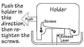
23-04-2000 TH-28/48/78 Difficult battery
insertion
Author: Kenwood
Communication, inc.
Service Bulletin no. 1028 (29 June 1993)
Symptom:
Insertion of the battery into the transceiver is difficult
or impossible due to problems with the release lever.
Corrective Action:
- A temporary cure is provide by loosening the two screws securing the
holder, shifting the holder to the extreme left, then retightening the
screws.
- A permanent fix is provide by replacing the holder and release level with
new parts that have been deburred and modified to allow relocation of the
release level.
Parts required:
Qty   Description                          Kenwood Part No.  Circuit description
 1    Holder                               J19-1515-23       NA
 1    Release lever                        D10-0610-13       NA
Time required for this modification is 30 minutes or less.
23-04-2000 TH-78A Microprocessor
change
Author: Kenwood
Communication, inc.
Service Bulletin no. 1038 (10 February 1994)
Symptom:
Due to a recent rule change by the FCC it is no longer
possible to supply transceivers, or provide replacement microprocessor that
would allow a transceiver to receive in the 800 MHz band.
Corrective action:
The microprocessor program of IC5 has been
modified to prevent 800 MHz band reception. Production has been changed
beginning with serial number lot 510xxxx. Units produced after this point will
not be capable of 800 MHz reception.
Parts required:
Qty   Description                Old part No.      New Part No
 1    Microprocessor             75517GF-170-3B9   75517GF-257-3B9
Procedure:
When ordering a replacement microprocessor you will be
supplied with the new version. Please make sure your customer understands the
limitations of this new