
19-07-1998 External DTMF Remote Control
The following procedure places the 733 in External DTMF Remote Control.
Note that this mode is different than DTMF Remote Mode. This mode concerns the control of the 733 with an HT, and not the microphone.
  ---------------------------------------
 I                     xx               I        xx meams [ 000 ]
 I  O                                O  I        O means hole of screw
 I                                      I
  ---------------------------------------
  on 144MHz              on 430MHz
     118-173MHz             118-173MHz
     130-173MHz             300-469MHz
     300-469MHz             800-900MHz
On 144MHz side , press [ MHz ] key more than 1 sec. , change mode for
AM.----------------------------------------------------------------------------- [#] PRESS A NUMBER, NOT THE POUND SIGN. [KEY] PRESS AND RELEASE [KEY] [KEY1]+[KEY2] PRESS AND HOLD [KEY1] DOWN, THEN PRESS [KEY2] [KEY1],[KEY2] PRESS [KEY1] MOMENTARILY, THEN PRESS [KEY2] [KEY]+[PWR] WITH POWER OFF, PRESS AND HOLD [KEY] THEN HIT [PWR] [KEY1]+[KEY2]+[PWR] YOU GET THE IDEA. [F] (1s) PRESS AND HOLD [F] FOR ONE SECOND. "F" THEN BLINKS. [KEY] (1s) PRESS AND HOLD [KEY] FOR ONE SEOND. [F],[KEY] (1s) PRESS [F] MOMENTARILY, THEN PRESS [KEY] FOR ONE SEC. -----------------------------------------------------------------------------The following entries are in alphabetical order.
1 MHZ/10 MHZ TUNING TOGGLE              [VFO],[F]+[MHZ]
ADVNACED INTERCEPT POINT (AIP)          [F]+[A.B.C.]
ALL LOCK                                [F],[MHZ],[PWR],[F]+[PWR]
AM/FM MODE                              [MHZ] (1s)
AUTO DIMMER CHANGE                      [F]+[LOW]+[PWR]
AUTOMATIC BAND CHANGE (A.B.C.)          [F],[A.B.C.]
AUTOMATIC OFFET (CANCELLING)            [VFO]+[REV]+[PWR]
AUTOMATIC POWER OFF (APO)               [F] (1s),[MHZ]
AUTOMATIC SIMPLEX CHECKER               [REV] (1s)
AUTOMATIC SQUELCH                       [MHZ] + [PWR]
AUTOMATIC TONE FREQUENCY ID             [TONE] (1s)
BAND SCAN                               [VFO] (1s)
BEEP LOUDNESS                           [F] (1s),[BEEP]
BLANKING A BAND DISPLAY                 [F] (1s), [BAND SEL]
CALL CHANNEL CHANGING (ODD SPLIT)       (RX FR),[F],[C.IN] (1s),(TX FR)[CALL]
CALL CHANNEL CHANGING (SIMPLEX,DUPLEX)  [F],[C.IN]
CALL CHANNEL RECALLING                  [CALL]
CALL/MEMORY SCAN                        [MR],[CALL] (1s)
CALL/VFO SCAN                           [VFO],[CALL] (1s)
CANCELLING AUTOMATIC OFFET              [VFO]+[REV]+[PWR]
CHANGING CALL CHANNEL (ODD SPLIT)       (RX FR),[F],[C.IN] (1s),(TX FR)[CALL]
CHANGING CALL CHANNEL (SIMPLEX,DUPLEX)  [F],[C.IN]
CHANNEL DISPLAY FUNCTION                [REV]+[PRW]
CONFIRMING PROGRAMMABLE LIMITS          [F]+[VFO],(L.SHOWN),[MR](U.SHOWN)
CTCSS                                   [TONE],TOGLE TILL "CT" APPEARS
CTCSS TONE FREQUENCY (SELECTING)        [F] (1s),[T.SEL],[UP]/[DOWN]
DIMMER (AUTO CHANGE)                    [F]+[LOW]+[PWR]
DIMMER (DISPLAY)                        [F],[DIM]
DISPLAY DIMMER                          [F],[DIM]
DISPLAY DOMONSTRATION MODE              [CALL]+[PWR]
DTMF CONFIRMATION TONES                 [PTT]+[DWN]+[PWR]
DTMF IN AUTOMATIC DIALER (STORING)      [F]+[CALL]+[PWR],{#'s},[PF],[#]
DTMF NUMBERS (RECALLING STORED)         [F]+[CALL]+[PWR],[MR],[#]
DTMF NUMBERS (TRANSMITTING STORED)      [PTT]+[PF],[#]
DUAL TONE SQUELCH SYSTEM (DTSS)         [F],[DTSS]
DUAL TONE SQUELCH SYSTEM (TONE SELECT)  [F] (1s),[C.SEL],[#],[SHIFT],ETC.
ERASING MEMORY CHANNELS                 [MR],[F]+[MR]
ERASING PROGRAMMABLE MEMORY             [F]+[PM],[#],[MR]
FREQUENCY READOUT BY BEEPS              [F]+[TONE]+[PWR],[PF]
FREQUENCY STEP SIZE                     [VFO],[F],[STEP]
FULL RESET (MINUS PM)                   [MR]+[PWR],[F],[MR]
FULL RESET (PLUS PM)                    [MR]+[PWR],[MR]
INITIALIZE FULL RESET (MINUS PM)        [MR]+[PWR],[F],[MR]
INITIALIZE FULL RESET (PLUS PM)         [MR]+[PWR],[MR]
INITIALIZE VFO BOTH BANDS               [VFO]+[PWR]
INITIALIZE VFO ONE BAND                 [VFO]+[BAND SEL]+[PWR]
LOCK (ALL)                              [F],[MHZ],[PWR],[F]+[PWR]
LOCK (TRANCEIVER)                       [F],[MHZ]
LOCK (TRANSMIT BAND)                    [F],[BAND SEL]
LOCKING OUT MEMORY CHANNELS             [MR],[F] (1s),[MR]
MEMORY CHANNELS (LOCKING OUT)           [MR],[F] (1s),[MR]
MEMORY ERASING CHANNELS                 [MR],[F]+[MR]
MEMORY RECALLING CALL CHANNEL           [CALL]
MEMORY SCAN                             [MR] (1s)
MEMORY TO VFO TRANSFER                  [F],[VFO]
MEMORY WRITING (ODD SPLIT)              (RX FRQ),[F],[MR] (1s),(TX FRQ)[MR]
MEMORY WRITING (SIMPLEX, DUPLEX)        [F],(FREQ),[MR]
MUTE                                    [MUTE]
PACKET BAUD RATE TOGLE                  [F]+[STEP]
POWER OUTPUT                            [LOW]
PROGRAMMABLE BAND SCAN                  [F]+[VFO],(L.FRQ),[MR],(U.FRQ),[MR]
PROGRAMMABLE LIMITS (CONFIRMING)        [F]+[VFO],(L.SHOWN),[MR](U.SHOWN)
PROGRAMMABLE MEMORY (ERASING)           [F]+[PM],[#],[MR]
PROGRAMMABLE MEMORY (RECALLING)         [PM],[#]
PROGRAMMABLE MEMORY (STORING)           [F],[PM],[#]
PROGRAMMABLE MEMORY SCAN                [PM]+[PWR],[PM] (1s)
RD OUTPUT SQUELCH CONTROL               [TONE]+[PWR]
RECALLING MEMORY CALL CHANNEL           [CALL]
RECALLING PROGRAMMABLE MEMORY           [PM],[#]
RECALLING STORED DTMF NUMBERS           [F]+[CALL]+[PWR],[MR],[#]
RECEIVE AUDIO SWITCHING                 [F] (1s) [CONT SEL]
REMOTE CONTROL MODE                     [F]+[CONT SEL]
S-METER SQUELCH                         [F] (1s), [S.QSL]
SCAN (BAND SCAN)                        [VFO] (1s)
SCAN (CALL/MEMORY)                      [MR],[CALL] (1s)
SCAN (CALL/VFO)                         [VFO],[CALL] (1s)
SCAN (PROGRAMMABLE BAND SCAN)           [F]+[VFO],(L.FRQ),[MR],(U.FRQ),[MR]
SCAN (PROGRAMMABLE MEMORY)              [PM]+[PWR],[PM] (1s)
SCAN MEMORY                             [MR] (1s)
SCAN RESUME TOGLE (CO, TO)              [F] (1s),[VFO]
SELECTING A CTCSS TONE FREQUENCY        [F] (1s),[T.SEL],[UP]/[DOWN]
SQUELCH (AUTOMATIC)                     [MHZ] + [PWR]
SQUELCH (RD OUTPUT CONTROL)             [TONE]+[PWR]
SQUELCH (S-METER)                       [F] (1s), [S.QSL]
SQUELCH HANG TIME                       [F]+[DIM]
STORING DTMF IN AUTOMATIC DIALER        [F]+[CALL]+[PWR],{#'s},[PF],[#]
STORING PROGRAMMABLE MEMORY             [F],[PM],[#]
TIME-OUT TIMER                          [F] (1s),[TOT]
TONE ALERT                              [F],[T.ALT]
TONE ALERT - CHANGE TONE                [F]+[SHIFT]+[PWR]
TRANCEIVER LOCK                         [F],[MHZ]
TRANSMIT BAND LOCK                      [F],[BAND SEL]
TRANSMITTING STORED DTMF NUMBERS        [PTT]+[PF],[#]
UHF+UHF OPERATION                       [F],[CONT SEL]
VFO TUNING LIMITS                       [F]+[C.IN],(L.FRQ)[MR],(U.FRQ)[MR]
VHF+VHF OPERATION                       [F],[CONT SEL]
WRITING MEMORY (ODD SPLIT)              (RX FRQ),[F],[MR] (1s),(TX FRQ)[MR]
WRITING MEMORY (SIMPLEX, DUPLEX)        [F],(FREQ),[MR]
If you have additions or corrections to this file, please send it to Brad
Killebrew N5LJV at [email protected], or packet
n5ljv@f6cnb.#setx.tx.usa.na. Green jumper wires (B2, B3)
_______ ___ ___ ___ ___ ___
-| |- | _ | | _ | |_ _| |_ _| |___|
-| XRU |- B0| | B1| | B2 | B3 |
-| 4066BF|- |_| |_| _|_ _|_ ___
-| |- |___| |___| |___| |___| |___|
-| |- _______
-| |- -| |-
-|_______|- -| |-
-| |-
-| |-
-| |-
-| |-
-|_______|-
The jumpers are actually soldered on the other side of the board, but the
loops come up over the top and hang over the B0/B1
side.Symptom:
Transmitted PL tones at the receiving station have a
relatively high level of distortion. This is easily seen when the incoming
signal is viewed on an oscilloscope.
Countermeasure
Change the value of the "Pull-up" resistors in the
PL tone encoder circuit as shown in the accompanying chart and illustration.
This reduces the distortion from around 9% to approximately 4%.
  Part  OLD value  NEW value
  ----  ---------  ---------
  R542  1.8k       2.7k
  R543  1.8k       3.3k
  R544  1.8k       4.7k
  R545  1.8k       6.8k
  R546  1.8k       10k
  R547  1.8k       10k
  R548  1.8k       10k
Procedure:
     TX-RX Unit (X57-4360-00)     Foil Side View
---------------------------------------------------------------


                                R  R  R   R542
                                5  5  5
                                4  4  4   R543
                                7  6  4
                                          R545
   (IC403 on component side)      R
                                  5
                                  4
                                  8       _______
                                        -|       |-
                                        -|       |-
                                        -|       |-
                                        -| IC402 |-
                                        -|       |-
                                        -|       |-
                                        -|_______|-
Caution: This modification requires advanced surface mount soldering equipment that is rated for CMOS circuits. It also requires familiarity with advanced surface mount soldering techniques. If you do not have the proper equipment or knowledge do not attempt this modification yourself. Seek qualified assistance from your closest Kenwood Service Center (Long Beach, CA, or Virginia Beach, VA).
The Service Manual specifies a test for the PL. The technician is simply required to verify that any one PL tone is between 500 and 1500 Hz deviation. This is quite a wide tolerance range! The "standard" PL tone deviation should be 750 Hz. Twice that strong might be too strong and become audible. There are no trim-pots on the PL deviation, so I'm guessing that the deviation is pretty constant from radio to radio.
The dirty PL is definitely found on early models, but we have had many reports that the PL problem has been fixed in newer versions of the radio. If you purchased your radio after September 15, 1994, (or your serial number is greater than 55000000) it's a good chance that you may not have the PL problem.
The other problem concerns the DTMF Confirmation Tones. This feature is off by default (I wonder why :), while it seems pretty useful. To turn it on, press [PTT] + [Down] on the microphone while powering the radio on. This will generate short DTMF confirmation tones whenever you send DTMF over the air from the keypad. Unfortunately, it mangles the beginning of the outgoing DTMF tone! This is serious enough that most local repeaters can't detect the tone, or count it as two tones.
Get a receiver and listen to what you are sending out when the Confirmation tones are enabled. It sounds to me like they may be mixing the confirmation tone in with the real tone and getting some destructive interference. Just a guess, though.
I called a Kenwood technician (Ricardo) and worked with him on the phone to reproduce the problem there. So, as of today, this is a Known Problem, and they are looking into a fix. :-)
I am really curious to know what they would say if other folks called up and complained about this problem. Would they deny hearing about it, or would it really be a Known Problem? Might give some insight into the PL-noise denial thing anyway. :-)
Personally, I'm much more concerned about the noisy PL than the DTMF
confirmation tones, since I can just shut those off and pretend that feature
doesn't exist. If enough people call about the PL problem, maybe they will come
out with a real fix and offer it under warranty to all the radios out there
(since they're all pretty new). My guess is that it will involve a free TSU-8
tone decode module, but don't hold your breath. :-)
19-07-1998 External DTMF Remote
Control
The following procedure places the 733 in External DTMF
Remote Control.
Note that this mode is different than DTMF Remote Mode.
This mode concerns the control of the 733 with an HT, and not the
microphone.
          1               2               3               A
       T.ALT ON         TONE ON        CTCSS ON         ENTER

          4               5               6               B
       T.ALT OFF        TONE OFF       CTCSS OFF       TONE SEL

          7               8               9               C
         CALL            VFO           MEMORY        REPEATER ON

          *               0               #               D
         DOWN        POWER LEVEL         UP          REPEATER OFF
    o  o
   o    o
    o  o
On the booklet it saysSymptom:
When transmitting a PL tone a "humming noise" might be
heard coming from the internal speaker of the TM-733A. This caused by a
difference of potential between the tone generating circuit and the AF amplifier
circuit.
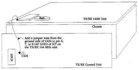
Countermeasure:
This symptom is corrected by tying the ground
connections in the AF amplifier and Tone generating circuit together.
Parts required:
Qty   Description              Old part No.   New Part No.
 2    Screw                    N87-2606-46    N87-2608-46
 2    star washers                            N16-0026-46
 1*   Small gauge hookup wire
Procedure:
Caution: This modification requires soldering equipment rated for CMOS type circuits. It also requires familiarity with surface mount soldering techniques. If you do not have the proper equipment or knowledge do not attempt this modification yourself. Seek qualified assistance from your closest Kenwood Service Center (Long Beach, CA, or Virginia Beach, VA).
Time required for this modification is 30 minutes or less.