New Parts:  10pf CC45SG1H100J
            18pf CC45RG1H180J


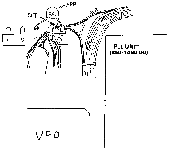
Some TS-120S users may complain of a hum during SSB operation, which may be
caused by RF feedback. There may be various reasons for this complaint.

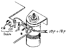
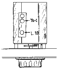
VFO drift characteristics may be improved by changing component values and location in the VFO.
This change applies to serial numbers before 00100001.
Note: DO NOT disturb lead dress or component placement while working inside the VFO.
New Parts: 10pf CC45SG1H100J
18pf CC45RG1H180J
|
 |
Analog Dial Calibration:


High speed CW ops may inquire about partial loss of the first character when operating VOX-CW. The transceiver will operate up to about 20WPM before this is apparent.
Improvement may be had by changing three components on the RF Unit X44-1260-01.
Production later than serial # 940701 has this change.
Please notate your Service Manual.


When ordering single replacement 2SC2290 Final transistors for the TS-120S,
please specify the hfe rank, by color. When replacing pairs of finals, always
select the same hfe randk for both transistors.
Rank designation will be
found printed on the transistor, directly under the transistor number.
Rank:     R    30-65
          O    55-95
          Y    85-150
Please return all defective 2SC2290 finals to the attention of the TRIO-
KENWOOD service department, along with the warranty claim form.
Old part number:    L34-0696-05    Antenna Coil
New part number:    L34-0696-35
Old Capacitor was 15pF, replace with
New part number:    CC45RH1H330J   33pf

Symptom                  Repair

No CW, No Audio          Sidetone oscillator Q25 on AF GEN unit 2SC1815
Receiver Sens Down       T1, L34--696-35 on RF unit Shorted
Analog Dial Cal OFF      Mechanical Adjustment
Carrier in SSB           RF unit D2 and D3 shorted see TKC Service Bulletin
Loss of Digital          Check P5/J5 on Carrier Unit
Smoke at Final Unit      Check for long eds of wire shorted to case inside
                         final unit also burned L10 and L11, L40-1011-04
                         (100uH)
SSB Audio bad            IF shift control turned max CW
Power on Meter Max       The RF gain control was turned max CCW
VFO freq drift           Replace the TEMP comp CAP C17
TX Audio BAD             Check the Carrier Point adjust and make sure final
                         bias is set to 150 Ma
PLL digital NG           Check D15 PLL unit
High IC in RX            Check the Final transistors
15 Meters only           The BCD rotary band switch has a broken wafer.
RX TX only 10M           The BCD divider Q16, 74LS163 on PLL unit bad.
                         Check the BCD inputs against the pin 2 frequency.
28.5 HF Osc              Check ground screws and tighten at Relay Unit X41-
                         1250
No CW Filter             Solder short across pins 1-2 J29 IF Unit
No RX                    After the CW filter was installed the pins were
                         not cut off shorting the signal to ground.
Analog dial off          Perform VFO tracking adjustment at 50 and 450
TX out 40M only          40M 50W and 10M 10W bad finals
No 15M                   Core on the VCO transformer for 15M broken
3.5 and 7 Band same      Shorted trace at Band switch under IF unit
Low RF out               All bands, Q12 SN16913 on AF gen unit, 2SK19GR bad
No TX all bands          L25 open on the RF unit Small gree inductor
No digital no TX         Q12 mixer on the PLL unit bad
No RX no digital         Q26 mixer on PLL unit bad
INtermitt SSB AUdio      Pin 5 of J5 on AF GEN unit loose
No key or TX             D26 and Q24 2SA562 on AF gen unit bad
No TX                    R8 220 ohm at key jack burned open.  Make sure
                         customer uses shielded line on CW KEY.
15M osc.                 On 15M band only with antenna HF oscillation when
                         first speaking.  Install Ferrite bead on base of
                         first mic amp Q18 AF GEN UNIT.
No TX                    Loss of AVB Voltage at RF unit.  Check Q9 2SA473
                         on the filter unit, also check 6 volt Zener diode.

For complaints of out of band interference, especially BCI, the BPF (Bandpass filter) terminating resistors may be changed for an improvement of approximately 10dB.
On the RF unit X44-1260-01 change R3,5,7,9,11 from 1.5K ohm to 470 ohm. No
adjustments are required.
19-07-1998 TS-120S TX
oscillation
Author: Trio-Kenwood
Communication, inc.
The TS-120S may exhitbit intermittent oscillation on the 15M, 10M and/or 20M bands. Symptoms may be no control of Carrier level, full current or ALC in either CW or SSB after initial keying or modulation, or "full output both forward and reflected".
R47 (33 ohm) change to 10 ohm Radial            (RD12CY2E100J)
R50 (560 ohm) change to 680 ohm Radial          (RD12CY2E681J)
C61 (220 pF) Remove
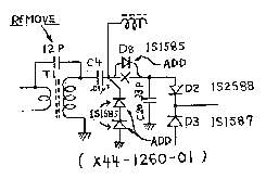
Add 2 1S1587 (V11-0370-05) diodes in series, anode to ground from the junction of C4 and D8.


Note: Installation time for this procedure is approximately ½ hour.

19-07-1998 TS-120S
Full CW output in ssb mode
Hight reverse leakage, ou shorting of
D2 and sometime D3 on the RF UNIT X44-1260-01, will provide an unwanted DC
voltage path which gives full CW output while in the SSB mode. Carrier control
has no effect, and RX is not affected.
Replace D2, 1S2588, check D3,
1s1587, and install an additional diodo, D8, a 1S1585 on the foil side of the RF
unit.
To install, swing the rf unit up. Remove the shield from under the
IF unit, exposing the foil side of the RF unit.
Using a razor or X-ACTO
Knife, carefuly cut the land between C4 and C20. Solder the additional 1S1585
across the the cut and observe polarity Replace D2, the 1S2588. Some RF units
have a 12 PF cap soldered on the foil side of the board, across T1; C20 will be
missing.
Remove the 12 PF cap, and install C20, 33 PF in the
board.
Production later than 080001 has this change.
14-01-2000 TS-120V: Reduced RX current
consumption
Author: Joachim
Seibert - [email protected]
The TS-120V is equipped with a two bulb lightshow. Remember that the chassis
really warms up above the VFO-scale and the S-meter...
I replaced the two
bulbs with green ultra-bright LEDs and matching resistors in series. The
resistors give you a chance to adjust a pleasant illumination level (I always
felt the lightbulbs beeing to bright). As standart LEDs are a little thicker
than the original Kenwood bulbs one need to cut off a part of the VFO-scale
lighting rubber mounting sleeve's rear portion. Cut of the bulb's wires close to
the glas body, they will perfectly serve the new LED-R
combinations.

Kenwood recommends the PC-1 Phone Patch for all of our radios. Most other phone patches will work satisfactorily without any modification to the radio, requiring only an external speaker connection, and that the Mic line be run through the patch.
For those operators who desire a Patch input similar to the TS-520S or TS-820S, an input connection and terminal must be added at the Mic input preamp circuit.
Fixed Divider
Use a 100Kohm in series, with a 10Kohm to ground on the input side of the 100Kohm resistor. Use shielded line, and connect as follows:

TS-120S
On the IF Gen unit X49-1110-01 install the fixed divider at the junction of R43 10K, C42 100pF, & C43 1uF (input of Q18). Add an RCA jack, or use remote pins 7 and ground for input.
TS-180S
On the IF Gen unit X48-1240-00 install the fixed divider at the junction of
R167 10K, C128 .001uF, & C129 1uF (input of Q32). Add an RCA jack, or use
remote pins 7 and ground for input. 
20-02-2000 TS-120S Final
protection
Author: Trio-Kenwood
Communication, inc.
If for any reason work is performed in the Final unit, install two additional parts to the Filter unit X51-1200-00. This will improve protection action.
Procedure:
No adjustment are necessary
New part number D14 1S1555    V11-0076-05
                R34 4.7Kohm

Please notate your Service Manual 
19-03-2000 TS-120S Ant input transformator
replacement (2)
Author:
Trio-Kenwood Communication, inc.
TS-120s Ant Transformator Replacement: New Part.
Supercedes bulletin #40 7/12/79
Transceivers subject to strong static fields, high RF, or similar high current atmospheric discharges may suddenly exhibit low sensitivity on all bands. TX will not be effected. Suspect T1 on the RF unit, X44-1260-01.
When replacing T1, L43, 0696-35, check that the value of C20 is 33pF. Early units may have a 15pF for C20, and may have T1 as L43-0696-05. In either case, replace the transformer with an L43-0929-15. If C20 is 15pF, replace it with a 33pF capacitor. Since T1 is a broadband transformer, no adjustment is necessary.
In addition, add two 1S1587 diodes after the transformer as shown to further protect the receiver.
Installation time for this procedure is approximately ½ hour.

