Modifications for the Kenwood
TS-140

19-07-1998 TS-140S Sidetone
Mod
I recently purchased a Kenwood TS-140S after using it on CW
for about a week, I decided to try it on SSB and AM. When I pushed the AM and
SSB mode switches, I heard a constant audio tone emanating from the rig. As I
diconnected the rig, preparing to return it to the factory, the tone
stopped.
Investigating the circuit diagram, I noted that the CW key has to be
unplugged to kill the sidetone. There is no mention of this in the Instruction
Manual.
Perhaps my experience may save others the frustration I
encountered.
Also, amateurs should pay attention to the proper use of
receiver noise blankers. I know of instances where operators were handing out
reports of distorted signals to outhers, only to discover that it was their
improper use of the receiver noise blanker that was producing the
distortion...
Ed, W6XM

19-07-1998 TS-140S Intermittent loss of TX
power
Author: Trio-Kenwood
Communication, inc.
Service Bulletin no. 928 (11-4-1988)
In some TS-140S transceivers, the drive transistor, Q2, is not firmly mounted
to the heatsink. This can cause a loss of transmit power after the unit warms
up. The following modification will correct this condition.
- Disconnect the TS-140S from the antenna and power supply.
- Remove the top and bottom covers. Open the sub-chassis. Refer to the
instruction manual for step by step instructions.
- Remove the shield plate from the sub-chassis (12 screws) to expose the
filter an final units. Do not loose the 2 springs that are secured by the
right side screws.
- Resolder Q2 so that the transistor makes firm contact with the heat sink
on the Final unit. Tighten the transistor's mounting screw. (See the diagram
below).
- Assemble the transceiver by reversing steps 1 through 3.

This modification may be performed under warranty.
Time required for this
change is 1/2 hour or less.

19-07-1998 Broadcast Sensitivity Modification
for the TS680S / 140S
Between .500 and 1.6 MHz attenuation is
added to reduce? front-end overload on the Broadcast band. Some of us BCB DXers
find this a HIGHLY undesirable feature. If I want attenuation I will use the
front panel switch. The following mod will restore the sensitivity -
Cut the
land between IC1 pin 11 and R7 (SIGNAL UNIT, M54581P)
Cut the trace
between IC1 pin 12 and R10
Add a small signal diode (1N914, 1N4148)
between IC1 pin 11 and R7 (Cathode towards R7)
Add a small signal diode
between IC1 pin 12 and R7 (Cathode towards R7)
Trace the lands from pin
11 and 12 of IC1 and you will find a good place (to the left of connector CN5)
to cut these traces as well as pad to solder the diodes to.

19-07-1998 TS-140S TX All Freq
Mod
To enable the TS-140S for transmitting on all bands:
- Disconnect radio from power supply and antenna
- Remove top and Bottom covers
- Locate the control board (I believe it is on the bottom --NOT BEHIND TH
THE KNOBS LIKE THE 440!!)
- Cut D31 on the control board
- Reassemble the radio
- Reset the radio by holding the A=B switch while powering up the rig.
Disclaimer: This Modification is for those who need it to operate MARS
only.

16-04-2000 TS-140S
Momentary transmission when VOX is turned on
Author: Trio-Kenwood Communication,
inc.
Service Bulletin no. 929 (11-4-1988)
When the VOX switch is turned on immediately after the power switch is
depressed, the TS-140S may trip into the transmit mode. This condition can be
corrected be changing the value of chip capacitor C504 on the Signal unit. The
following procedure will detail how to access the capacitor.
Required parts:
C504 0.001µF, 50V chip capacitor (CK73FB1H102K)
- Disconnect the TS-140S from the antenna and power supply.
- Remove the top and bottom covers (12 screws). Remove the 4 sub-chassis
mounting screws. Swing the sub-chassis to the left to expose the Signal unit.
If required, refer to the instruction manual for illustrations.
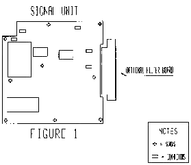
Note: Refer to figure 1 for the next steps.
- Unplug the wires at connector CN4, CN12, CN18, CN19, and CN20.
- Remove the nine screws from the signal unit.
- Slide the Signal unit forward until the external speaker jack clear the
back panel cutout.
- Carefully lift the Signal unit up from the back side and rotate it toward
the front panel to expose the bottom of the board.
- Locate chic capacitor C504 on the bottom of the board (see figure 2). If
required, refer to the service manual board diagrams for details.
- Unsolder and remove the C504.
- Install and solder the .001 µF capacitor in place of C504.
- Assemble the transceiver be reversing the above steps.


This modification may be covered under warranty.
Time required for this
modification is 1 hour or less.


