Modifications for the Kenwood
TS-690

19-07-1998 TS-690 50 MHz modulation problem
solved
Some time ago I reported a (severe) problem with SSB
modulation quality on 50 MHz of the TS-690S. There is now reason to believe that
the cause of this problem has been identified and thus the problem can be
solved.
Thanks to Mike Gotch, G0IMG, it became clear that the bias
voltage on pin 3 of the 50 MHz driver module (Mitsubishi M57735) is too low.
This voltage is 8 V or less in the TS690, whereas the manufacturer specifies a
voltage of 9 V minimum. Mike also proposed a simple modification to increase
this voltage to the appropriate level (to be published in SIX NEWS of
January).
I have forwarded this information to my dealer (Schaart in
Katwijk, The Netherlands). They did some thorough testing and came up with a
similar circuit as Mike, which can be implemented on the driver module PCB. The
basic schematics of the mod are given below.
Remove copper between
50T of CN3 and C7 on 10W final unit (X45-3420-00) (this means that line 50T to
Q1 of the driver PCB is NOT cut). Add the following circuit.
                                          ------------ 14S of CN3 (13.8V)
                                            |      |
                                           ---     |
                                           | |R4   |
                                           | |     |
                                           ---     |e
                                      ___   |    |/
                                  ---|___|-------|  Q2
                      R1          |c  R3       b |        _______
                      ___     b |/                 |c     |       |
term. 50T of CN3 >---|___|----- |  Q1              -------| IC1   |--> to p.3
                           _|_  |                        |_______| of module
                           | |    |e                          |     M57735
                       R2  | |    |                           |
                           ---    |                           |
                            |     |                           |
                            ------------------------------------- GND

R1 + R2 + Q1 = DTC114  or  R1= 10k, R2= 10k, Q1= BC547 (NPN, Ic max= 100mA)

R3 = 3k3, R4 = 10k, Q2 = 2SA984 or BC327 (PNP, Ic max= 500mA)

IC1 = 7809 (1.5 A version in TO220 envelope)
IC1 can be located near CN1 with the metal side towards the cast alu.
heatsink.
All other components can be located on the foil side of the PCB
near CN3.
With this mod the known mod (STR nr. E51-92-038) of L20 on the IF
board (100 uH -> 10 uH) is not necessary anymore.
In some cases the
TS690 tends to oscillate. This is due to the critical wiring in the filter unit.
Especially the 2 blue wires of CN7 need to be redirected away from the 50 MHz
band filter. Even a ferrite bead might be needed to prevent RF feedback. Also
the grey thin coax from CN5 which is folded near to the black relay K15 might
cause RF feedback. The folded length of coax must be redirected outside the
filter compartment.
This modification has been published by my dealer,
and will be forwarded it to Kenwood Brussels. How long it takes to get
acknowledged by Kenwood Japan is not clear...
If you are interested I can
sent you a copy. Please send a SASE + 1 IRC or SAE + 2 IRC's/1 US$ to me and you
get the copy as soon as possible. If you do not feel comfortable to implement
this mod yourself, contact your local dealer.
If you or your dealer needs
advice on the mod, please contact Schaart (tel. +31.1718.15708, fax.
+31.1718.73143).
Good luck and enjoy 50 Mhz with your improved
TS690.
Enno J. Korma, PA0ERA
P.O. Box 6687
6503 GD Nijmegen, The
Netherlands
19-07-1998 General coverage transmisson
modiication for the TS-450 and TS-690
- Remove all screws of top and bottom case.
- Remove two screws of front panel (left and right top sie),and loosen two
srews of front panel (left and right bottom side).
- Remove all screws of digital unit ( X46-312X-XX ).
- Cut the chip diode D27 (RL73) on digital unit rear side.
\\\\\\\\\\\\\\\\\\\\\\\\\\\\
[      \                                              [
[   \__  __                                           [
[  \_ Bat. _                                          [
[   [      [                                           [
[    __\__                 \\\\\\               [
[              \\        [          [               [
[    [_\_[     [   [        [          [               [
[    [   [     [  [        [          [      ->I- D27 (RL73) CUT THIS
[    [   [     __ __        [\\\\\_      ->I- D26
[    [\[                                    ->I- D25 [
[                                             ->I- D24 [
[                                             ->I- D23 [
[                                             ->I- D22 [
[                                             ->I- D21 [
[                                             ->I- D20 [
________________________________________________________
DIGITAL JNIT (X46-312X-XX)     Component side view
Best 73 Eric St-Pascal Kam. Qc. VE2MEL
20-02-1999 Micro-input RFI modification
TS450-TS690 Kenwood
By Pedro M.J. Wyns, RF- and
biomedical-engineer.
History:
After buying a ts690 I got
considerable trouble with the vox circuitry.
The Vox gain was always too high
due to an excessive feedback resistance in the vox amplfier. Apparently a
PCB-mounting failure as the schematic carried the right value. After correcting
this problem I still got RF problems with nearby antennas, blocking the
transmitter in TX.
Problem:
lack of decent RF-filtering on the
micro-input circuitry.
Solution:
adding ferromagnetic cores and
adjusting rc-filters on the IF-board.
Action:
remove the connectors on
the right hand side of the IF board (underside transceiver front towards you).
Unscrew the board and fold over to the left. Add 22 nF parallel to R282 1k on t
he micro entry close to Connector 6. Add 1nF parallel to C177 close to the IC-15
input. Add 1nF parall el to C217 close to the vox amplifier.
Remove te micro
in and ground from the number 6 connector. Feed the white micro wire through a
two hole ferrite core. Feed the inner conductor through a small ferrite core as
well Reconnect...
If you might be using an MFJ (=major fucking junk)
voice keyer, disconnect the shit-unshielded micro cable and replace by high
quality twin balanced micro cable. Only use PTT, Mic and GND.
This
concludes the mod. Don't even think of doing this without the service man ual
and some smd-practice.
Good Luck
Pedro M.J.
Wyns
[email protected]
Moutstraat 7
B-2220
Hallaar
Belgium-Europe
Fax +32 15 303115
26-09-1999 TS-690S 30KHz-60MHz
RX
Hello all TS-690 owners. I finally found the mod I was looking
for. I've never seen this mod anywhere before I suddenly found it on G4ICD
web-site today :-)
TS690 Mods. Mods for your Kenwood TS690 - by Tuomu
OH1LEU Six News..........
In issue 36 of Six News there was an article
concerning the Kenwood TS690. A few questions were asked. I hope the following
information will answer a few questions, including the 30KHz-60MHz coverage. I
have a 690 bought direct from the States and my friend Kari OH1MLD has one
bought from Finland.
We have been comparing the differences between models!
All band assignments are ontrolled by diodes in the digital unit, which is
located behind the front panel. There are several (probably) yellow 4148
look-a-like diodes in a row, marked D20-D23. D23 affects the rx range. Removing
it opens the receiver from 30KHz (yes!) to 60MHz continuously. Also any
frequency change can now be controlled directly from the keyboard. D20 may have
something to do with the WARC bands, at least in the US model there is only one
diode D21, so you might like to try taking others away. Also the logic changes
when entering a new frequency because of the "new bands", so be careful when you
decide to operate!
If you want to make these mods, take both covers off, note
the extra filters which are now the highest parts of the rig and note also that
those little flat cables coming from the digital unit can very easily break.
After that, loosen two lower screws (on both sides) that are securing the front
panel and take away the two upper screws. Now the front part can be twisted
downwards. Diode D23 can be removed easily from the digital unit PCB, located at
the right hand side. You may also like to make some changes to the mic gain
scaling. It is very easy to overdrive the PA. Between the mic gain pot an the
centre tap is a 10k resistor which causes the mic gain to be somewhat non-linear
pot, but, if for example I had the mic gain at 9 o'clock now I can turn it to
nearly 12 or even more. This is very handy when using the processor, the ALC
setting is now not as critical.
The maximum gain remains the same. You may
have noted that the AM band has poor sensitivity. You may change the coupling in
the RF-unit on that particular band 500KHz-1.6MHz. The coupling has two 39 ohm
resistors (R6, R7) in series, controlled through a 10 ohm resistor (R8) between
them. Changing the 10 ohms to a miniature coil 1uH and those 39 ohms to 0 ohms
makes AM sensitivity much better. If you live near an AM station forget this
mod! The SMD components are located in the RF-unit, from the CN4 connector and
IC2 towards the centre of the PCB, at the opposite end to the filters. I would
recommend the ourchase of a service manual before undertaking these mods. I can
also not be held responsible for any damage Hi! 73 de Tuomo
OH1LEU.
Note Cutting D23 reverts the 690 back to Japanese spec
i.e. full Rx coverage up to 60MHz but only 50w o/p on 10m due to their
regulations.
(Thanks G0HVQ)
There it is. I don't take any
responsibility for any damages on your radio, or violation of any regulations.
Perform the mods at your own risk. I haven't tested this myself. If you have any
questions, I can't help you, I'm just relaying it off the internet. 73 de
Andreas, LA8AJA.
21-04-2000 TS-450/690 Calibration cable
change
Author: Kenwood
Communication, inc.
Service Bulletin no. 995 (11 May 1992)
The TS-450/690 may not calibrate properly against WWW (JJY) when using the
calibration cable that is supplied with early versions of these sets, (serial
numbers below 311xxxx) and when an antenna that is shorted for DC is used. A
dipole with a balun is a prime example of a DC shorted wire. A minor circuit
modification that adds a 100 pF isolation capacitor should also be performed.
Please refer to the diagrams below for modification notes.
Parts required:
E37-0280-05      Calibration cable assembly         1 Ea.
CK73FCH1H101J    100 pF capacitor                   1 Ea.
Time required for this modification is 30 minutes.
22-04-2000 TS-450/690 Distorted TX
w/TNC
Author: Kenwood
Communication, inc.
Service Bulletin no. 1002 (18 November 1992)
Note: This bulletin supercedes bulletin ASB-994, dated 10 April, 1992.
We have received several reports of distorted transmitter audio when using a
TNC controller such as the AEA PK-232 or Kantronic KAM, etc. The symptom will
generally disappear if the transceiver and TNC units are powered from different
sources.
Cause:
The audio output level form the TNC is generally too high
and causes overload of the microphone amplifier circuit. In previous models such
as the TS-440S the incoming TNC audio was inserted after the microphone
amplifier. With the TS-850S it is inserted before the microphone amplifier. Just
moving the insertion point to the output of the circuit is satisfactory since
the drive level for FM packet is higher then that required for SSB.
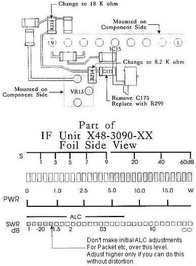
Procedure:
- Add a 10 dB attenuator to the PKD line on the IF unit (X48-3090-XX). This
will prevent overmodulation of the microphone input circuit.
- Change chip resistor R233 from 10 Kohm to 18 Kohm (RK73FB2A183J)
- Change chip resistor R234 from 1 Kohm to 8.2 Kohm (RK73FB2A822J).
- Delete chip capacitor C173 (100 pF) and add chip resistor R299, 1.5 Kohm
(RK73FB2A152J).
- Add the following note to page 35 and 37 of the Instruction
manual.
- When adjusting for proper ALC levels with an AFSK RTTY terminal or Packet
TNC terminal you should adjust VR-13 on the IF Unit for a reading similar to
the one shown in the accompanying diagram.
Note: The transceiver
and RTTY or TNC terminal should use separate power supplies, in order to
prevent RFI (Radio Frequency Interference).
Caution: This modification requires soldering equipment rated for CMOS
type circuits. It also requires familiarity with surface mount soldering
techniques. If you do not have the proper equipment or knowledge do not attempt
this modification yourself. Seek qualified assistance.
Time required for this modification is ½ hour or less.
23-04-2000 TS-450/690 Low mic gain
w/DSP-100
Author: Kenwood
Communication, inc.
Service Bulletin no. 1032 (9 August 1993)
Symptom:
Proper microphone gain/ALC readings cannot be obtained
unless the user adjusts the TX GAIN potentiometer on the rear of the DSP-100.
This irregularity is caused of the DSP-100 MIC amplifier (IC-5).
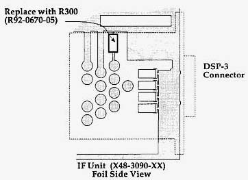
Corrective action:
Remove capacitor C200 from the IF unit on the
transceiver, and replace it with R300, a chip jumper wire.
Parts required:
Qty   Description                          Kenwood Part No.  Circuit description
 1    Chip jumper                          R92-0670-05       R300
Caution: This modification requires soldering equipment rated for
CMOS type circuits. It also requires familiarity with surface mount soldering
techniques. If you do not have the proper equipment or knowledge do not
attempt this modification yourself. Seek qualified assistance.
Time required for this modification is 1 hour or less.
23-04-2000 TS-450S/690S Noisy
encoder
Author: Kenwood
Communication, inc.
Service Bulletin no. 1059 (7 July 1994)
Symptom:
When tuning the Main Encoder of the TS-450S/690S with bare
hands you may encounter a "scratching" noise in the speaker if an antenna with a
high SWR is used. If gloves are worn no problem is encountered. This occurs
because the shaft of the encoder is not grounded.
Countermeasure: Replace the Main Encoder with one that has a grounded
shaft.
Parts required:
Qty   Description                          Part No.
 1    Main encoder                         W02-1836-05
 2    Mounting screws                      N90-3006-46
Note: You must use the new mounting screws listed above with the
replacement encoder.
Time required for this modification is 30 minutes or less.