The transmitter described is a modification of the original design by George Jacob (Lowfer 'GIR'). Thanks go to Mitch Powell (VE3OT) for providing circuit details. This is the same design currently used by Mitch and is the one I built for tests with Oregon and Alberta. This particular transmitter was later shipped up to VY1JA in the Yukon where, thanks to Jay's excellent antenna system, it was heard in Europe as well as in New Zealand during one of the Trans-Pacific Tests! Running 24 volts on the final will produce 100 watts into a 50 ohm load.
The transmitter utilizes a 4060 binary counter IC chip as both the crystal oscillator and frequency divider. I used a 2200 kHz crystal along with the 'divide-by' sixteen output to produce a signal at 137.5 kHz. Other combinations of crystal frequencies and 'divide-by' combinations may also be used since the 4060 features divided outputs for f/32 (pin 5) and f/64 (pin 4), among others. You may have a 4MHz crystal or an 8MHz crystal in your junk box that will put you in the band using these output pins.
I used a crystal oven from a very old taxi cab fm radio to mount the crystal but do not use the 'oven' feature. I discovered that the thermostat-controlled heating / cooling cycle produced more drift than simply leaving the oven off. I have however, lined both the inside and the outside of the oven with styrofoam in hopes of keeping the crystal's temperature change to a minimum. Initial tests indicate that it is entirely adequate for QRSS30 speeds. I have not yet tested it at QRSS60, where even the slightest drift shows up very quickly.
The transmitter is simple and inexpensive to construct. The IRF540 FET final runs very cool, although it should probably be heat sinked. I have also used IRF640s with little or no change noted. All coils and transformers are wound on ABS or PVC tubing.
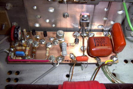
I used the "Manhattan Style" of construction on pc board.
Output Transformer (T1) - wound on 1.5" tubing ~ 5 inches in length. Wind the secondary first which consists of 80 turns of ~ #20 enamel wire. Wind the primary centered on top of the secondary with 15 turns of ~ #16 enamel, close spaced. Before winding the primary, wrap the center part of the secondary with PVC electrical tape or heavy plumber's teflon tape.
Output Filter (L1) - wound on 2" tubing ~ 5 inches in length. Wrap 80 turns of #20, close spaced with taps at 40 turns and every 5 turns until the end.
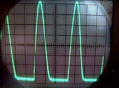
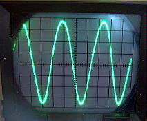
The capacitor used at the drain of the FET should be of high quality such as polycarbonate or mica. Although the original design indicated a 1 uF capacitor at the top end of T1's primary, I found that the 2.2uf gave a better waveform across the FET's drain. Look for the typical class-e type waveform at the drain.
Operation - Mitch's version of this amp appears to be operating at greater efficiency than the one I built. Running the final at 24VDC, the FET draws around 6.5-7 amps for an input of approximately 160W. With a measured output of 95W, the efficiency is around 60%. A properly designed class-e amplifier should realize much higher efficiencies so there is still plenty of room for improvement on this design. One of the things I would like to do is experiment with the output transformer in order to optimize its performance. Perhaps rewinding it on a ferrite core would help. The output transformer develops a lot of heat, indicating a substantial power waste. Perhaps that is where the missing 30% efficiency can be reclaimed.
Operate the transmitter into a 50 ohm dummy load or your resonant (50 ohm) antenna system. You might want to 'tune-up' at a lower voltage and then increase the drain voltage when adjustments are completed. Start with the antenna tapped at the coaxial end of the filter coil. As you tap closer to the center, power output will increase, as will final amplifier drain current. You will reach a point where the output does not increase any further, even though drain current has increased. Tap at the point of best efficiency. The output waveform should be a clean sine-wave.
I have run this transmitter all night long on several occasions, at QRSS30, and it has performed very well for such an easy design. I use a K1EL QRSS keyer chip to generate the QRSS beacon keying or the 'QRSS' freeware by ON7YD (available on his website).