BACKGROUND
I first heard of a 'Paraset' when I saw a message on the QRP-L reflector announcing an upcoming 'June 6th Paraset D-Day' activity. A search for more information soon revealed that the Paraset was a small vacuum-tube transmitter-receiver unit built during WWII in the UK at the Whaddon Hall headquarters of the Secret Intelligence Service Communications Unit. Known officially as the 'Whaddon Mark VII', the units were either air-dropped by parachute or carried, by the jumpers themselves, into many of the occupied countries of western Europe. Designed for quick deployment and low-power requirements, the radios consisted of a two-tube (6SK7s') regenerative receiver and a single 6V6 crystal power-oscillator capable of delivering 4-5 watts into a makeshift antenna. The transmitter-receiver combination could be used on any frequency between 3 and 8mHz and I suspect that most field-agents had a variety of crystals to try and stay one-step ahead of curious enemy direction-finders. Large rhombics and high power at the Bletchley Park control station assured that the field agents could reliably communicate using their little Parasets.Although many of the first Parasets were built in wooden cases, later versions were constructed inside metal boxes while some even turned-up in small leatherette 'suitcase' enclosures. Unfortunately there are very few original Parasets left and those that are still around are usually found in museums or in private collections.
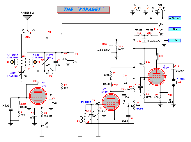
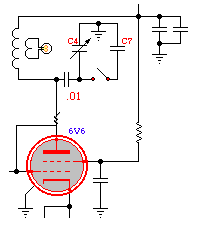
THE CIRCUIT
A look at the circuit schematic shown below will illustrate what is involved in making a Paraset.
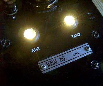
The single-tube 6V6 crystal oscillator utilizes an efficient dual-lamp visual tuning system to allow easy resonating of both the transmitter plate tank circuit as well as the antenna loading circuit. When properly tuned and loaded, both lamps will glow at full-brilliance. A separate padding capacitor (C7) is switched (S2) across the plate-tuning capacitor (C4) to accommodate resonating the plate tank circuit on the lower frequency ranges (80m) while a 2-pole 2-position rotary switch (S1) takes care of switching both the antenna and the B+ between transmitter and receiver. A small wire 'gimmick' capacitor (C3) provides sufficient feedback to allow the 6V6 to oscillate at the crystal fundamental frequency.
The two-tube receiver utilizes a 6SK7 oscillating detector to drive another 6SK7 audio amplifier. Regeneration is smoothly controlled by varying the detector's screen voltage (R5) while the second stage provides ample volume to a pair of high-impedance earphones.
CONSTRUCTION
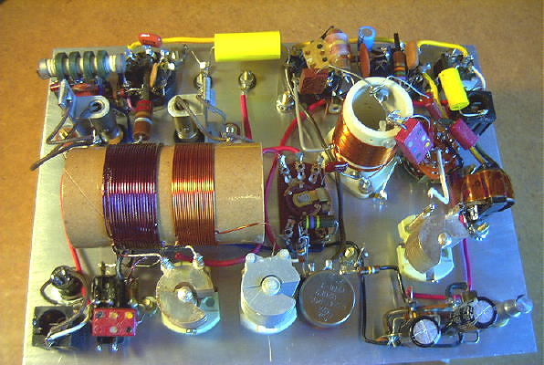
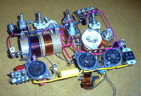
After gathering all of the information that I could find on Paraset construction, I found that my junk-box contained more than enough of the required old parts to begin building my own Paraset replica. The very active 'Parasetbuilders Group' on Yahoo Groups (see links section) provided the bulk of encouragement and the much-needed schematic details as well as dozens of great photographs of previously home-grown Parasets.
A piece of 1/8" aluminum plate (from a salvaged STOP sign) was chosen for the main panel and once all of the required holes were drilled, construction of the receiver section was completed. Much to my delight, the receiver came to life immediately with amazing sensitivity and good volume. I spent several hours just tuning around the bands to see what could be heard. Though not without its drawbacks, the simple receiver worked very well.
The transmitter section went together quickly as well and, like the receiver, worked very well right from the start. The power output was a little less than expected, at around 3.5 watts but a new tube and a small but important change (described later) brought things back to normal.
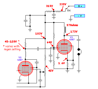
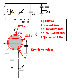
The homebrew power supply built for the project was only able to provide 295 volts which is a little less than desirable but enough to provide a solid 5 watts of QRP output from the 6V6 power-oscillator.The voltage parameters measured on the receiver section are shown below. These can be scaled-up or down if your B+ is significantly different:
The voltages measured on the transmitter as well as the operating parameters are shown here:
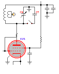
CONSTRUCTION HINTS The original design requires that the plate-tuning capacitor (C4) be insulated from the chassis as the plate voltage is present across the plates. The advantage of this is that a small receive-type variable can be used without any danger of arcing across the narrowly-spaced plates. I preferred to keep the rotor at ground potential to eliminate the shock potential and simply grounded the rotor as shown here:
If you wanted to go the extra mile and keep high voltage off the plate capacitor completely, use a blocking capacitor as shown below. This will also allow you to use a smaller receive-type variable for the plate cap without the danger of arcing between the plates.
While testing the receiver I had the opportunity to try various chokes for the 36H plate choke in the audio section. Almost everything I tried, from small audio transformers to small filament transformers, worked well, as long as the DC resistance was higher than 500 ohms. I ended up using a small AF transformer salvaged from an old vacuum-tube car radio.
One of the first things that I noticed when first testing the receiver was the presence of 'tunable hum' as well as a number of dead-spots throughout the tuning range. As well, the regeneration control was very sharp and instead of going into oscillation smoothly, would suddenly drop-in with a 'click'. A discussion of regenerative detectors in an old 'Jones Radio Handbook' indicated that all of the above conditions were often a result of over-coupling of the antenna circuit. I started reducing the value of C5 from the original 100pf value and eventually found that 10pf was ideal. There was still plenty of signal coupling into the detector but gone were all traces of tunable hum, dead spots and clicky regeneration. The detector now goes very slowly and quietly into regeneration without even a 'plop'.
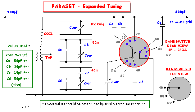
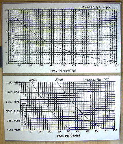
Another initial observation regarded receiver tuning. The large frequency range (3-8MHz) meant that fine-tuning was tough work. If the Paraset was going to be used as a 'working' radio then a slower tuning rate would certainly be required. Although I was able to work a number of stations using the original configuration, it was not a lot of fun. I found the bandspreading modification by KE3OQ (Electric Radio #179) to be particularly easy to implement and extremely effective in spreading out both 80m and 40m across the dial. As well, the mod still allowed the original full-tuning range to be retained. Michael's excellent bandspreading details are shown here:
The modification required only four small mica capacitors and a small rotary switch. Your coil and capacitor combination may require slightly different values from the ones shown but these will get you close.
Tuning calibration charts for both the main tuning range and the CW bandspread portions of 80 and 40m indicate the huge improvement gained with the bandspread mod.
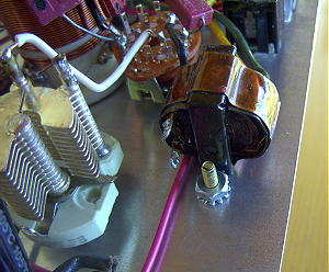
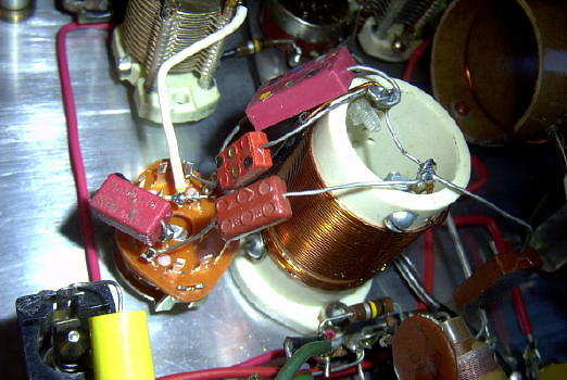
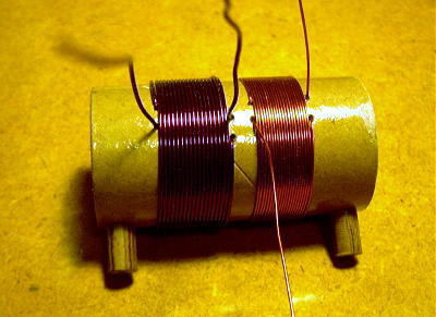
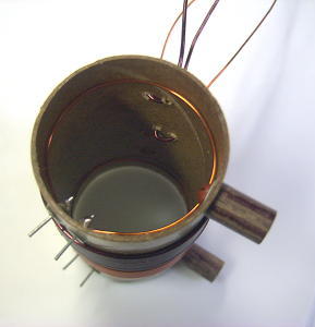
The coil form material for the transmitter was salvaged from the kitchen re-cycle box. The center-tube from a wax-paper roll was coated with several coats of varnish before winding the coils.
The one-turn pickup loops for the tuning bulbs can be seen here. The links were brought out through small feedthroughs designed for printed-circuit board use.
As mentioned earlier, the most output power I could get from the transmitter was about 3.5 watts. Changing to a newer 6V6 gave me another half-watt but still somewhat troublesome. I thought that perhaps my lower plate voltage (290 VDC) may have been the cause until I realized that the two tuning lamps, although fun to watch, were likely sucking-up valuable RF. A check of the #47 bulbs specs (6.3V / .15A) indicated that they were likely dissipating about 1.5 - 2 watts of power when at full brilliance and I would be much better-off putting that power into the antenna system. Substituting a #49 bulb of the same size (2.0V / .06A) gave me almost two more watts of measured RF output with no other changes required. You may however, want to make smaller pick-up links or put a little bit of resistance in the lamp lines if you are running more than 290VDC on the transmitter. When everything is tuned correctly, both bulbs will glow brightly, with the 'ANT' bulb being a little brighter than the 'TANK', indicating that your antenna loading is properly optimized.
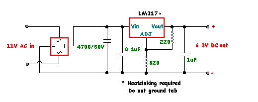
In my initial jubilation of listening to the amazing sensitivity of the regen receiver, I failed to notice that the CW signals were not perfectly clean and that some AC ripple component was evident. It really struck home one moment when the temporary clip lead to the AC filament supply became disconnected while listening to some CW signals. The filaments took several seconds to cool-down but during that time period the CW tones became the cleanest and purest notes that I had ever heard coming from a homebrew receiver! Attaching the clip lead again immediately brought back the AC note that I soon decided I would not be satisfied with. I quickly built-up a DC filament circuit that could be run from my existing power supply, by combining the 5V and 6V filament windings and regulating them with an LM317 regulator IC set for 6.3 volts. The filtering-action of the regulator eliminated all traces of AC and the CW notes became crystal-clear as noted earlier.
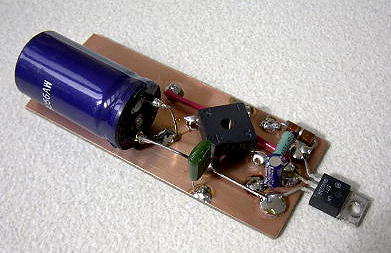
As luck would have it, I had just enough room inside the small power supply chassis to fit the Manhattan-style filament rectifier board. The chassis itself is used as the heat-sink for the IC regulator but must be insulated from the case.
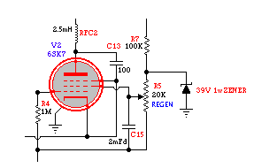
I have read a number of comments from Paraset builders indicating that their receivers were very unstable or jumped frequency when switching from 'transmit' back to 'receive'. I too noticed this condition but it wasn't a severe problem, just an annoying one. I eventually discovered that the 6SK7 tube used in the detector stage was the cause of the frequency shift when switching from 'transmit' to 'receive'. Evidently there were some inter-element expansion / contraction problems within the tube related to the cooling-down period while transmitting and then powering-up the detector when switching back to receive. A different 6SK7 did not exhibit any sign of the problem, resulting in no frequency shifting when going back to 'receive' mode. I did still have a problem with the receive frequency frequently drifting up or down several kHz whenever my line voltage changed. Living in a rural location, I have noticed that the line voltage will suddenly change by several volts from time-to-time. The change results in a small but noticeable change in the sensitive screen voltage which controls regeneration. Any change in this voltage also causes a corresponding change in the oscillator's frequency. A quick and simple cure was to clamp the top-end of the regenertion control (R5) with a 39V 1watt zener diode. The improvement was immediate as the stiff screen supply refused to budge even when the line voltage shifted. Once warmed-up, the receiver will stay put on its set frequency with no noticeable changes:
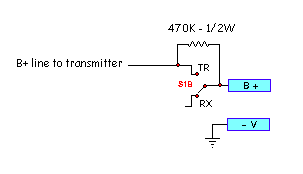
Another worthwhile addition that will make life easier for your CW operation, is the ability to spot your crystal frequency, while listening on the receiver. By always keeping a small amount of DC on the transmitter (even when in the receive mode), pressing the key will allow a weak signal from the crystal to be heard. Every crystal will react differently ... some will key nicely while others will 'almost oscillate' and in this case, a 'thump' or a 'click' will be heard on the crystal's frequency as the crystal attempts to go into oscillation. All of these will tell you where you are transmitting which is very helpful for knowing where to listen for callers. The 470K 1/2 watt resistor is a suggested starting point, since your B+ levels may be different than mine. Don't be afraid to adjust this value up or down somewhat.
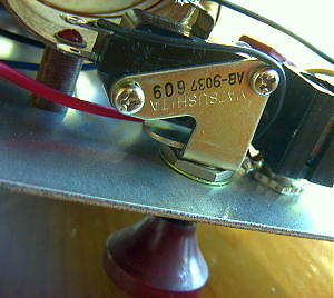
One of the last things I considered was the 'key'. Not wanting to construct an elaborate key that would likely not see much actual use, I chose a salvaged push-switch that seems to work well. A piece of yellow-cedar, turned on the wood lathe and sprayed red, was used to replace the switch's original plastic button. A separate 'key' jack was added to the panel, just below the built-in key.
An overall view of the Paraset's wiring can be seen below. Having poked and prodded the Paraset for several weeks, as well as having dozens of great contacts with it while on the workbench, the time had come to paint, bake and label the panel. This meant stripping all of the parts from the panel and dropping them out in one massive wiring harness. Everything went smoothly but it was something that I had been avoiding for as long as possible. Dan, W7OIL, another avid Paraset-builder, refers to this as the 'Stealth Model'.
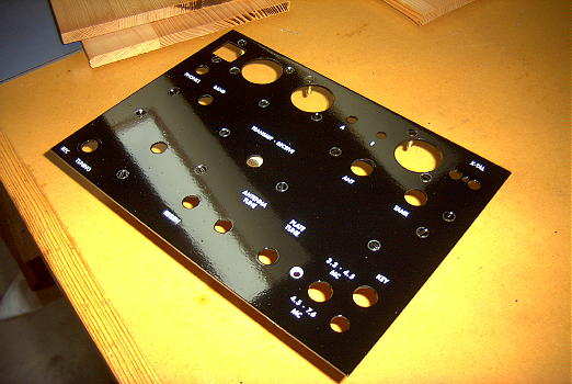
Once the parts were removed I was able to spray paint the aluminum panel with several coats of 'Tremclad Black Gloss' spray (Home Depot). I have found that a harder and shinier finish can easily be obtained if the panel is placed in a slightly warm oven after each coat and allowed to bake-on for at least 30 minutes. Since I am usually just painting small panels or chassis, the kitchen toaster-oven works well but be sure to turn it on at the lowest possible temperature as you do not want to get the metal too hot.
Once the panel was baked, dry-transfer lettering was applied, followed with a light coating of 'Tremclad Clear Gloss' to protect the transfers.
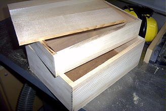
The final task was to build a suitable enclosure. A friend had given me some short Douglas Fir planks that I decided to mill and use for the case. A full-size box carcass was built and then cut to form the lid section, ensuring that the two parts would align properly once hinged:
OPERATING THE PARASET
When I first decided to build the Paraset I really didn't think that I would have much occasion to use it except, perhaps, during the annual 'Paraset Day' event. After ironing-out the few inherent bugs, I quickly discovered what an amazingly capable radio it really is and have been having a lot of fun operating it for the past few months. Most of my operating has been on 7034.5 kHz with my precious Bliley AX2 crystal and a 40m half-sloper wire antenna. On October 29th, 2008 I worked five-watter, W4TCO in South Carolina for state # 50, on 40m. After completing W.A.S. on 40m, I re-configured the 40m half-sloper for 80m operation and on Jan 25, 2010 I worked KB1KGA in NH for state #50 on 80m.
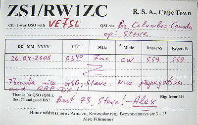
The biggest highlight so far was one evening in late April, just a few minutes before my local sunset. I heard a weak station replying to my slow hand-sent 'CQ' on 40m but just could not get enough of his call to reply. I sent 'QRZ' several times and signed my call. Once again the caller replied and this time I replied with 'W1ZC ??' and waited. He called a third time but had faded-up considerably now. I nearly fell off the chair when he sent, several times, 'ZS1/RW1ZC' ! Working South Africa from VE7 land is rare enough but with the Paraset it certainly was one of my most exciting contacts ever.
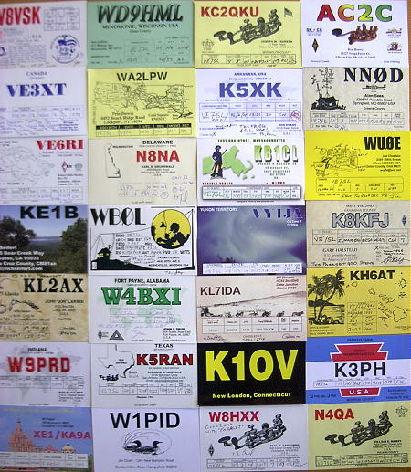
Here are a few of the stations that I have exchanged QSLs with following our Paraset QSO.
When I tune across 40m on a winter evening, using the Paraset receiver, I am reminded of the wonderful passage on p.73 of the 1931 Radio Amateur's Handbook. It is the closing paragraph in the 'Receivers' section:
"And now, when the receiver has been built, adjusted, and placed in satisfactory working condition it will be permissible to sit back and take a long breath. For the receiver is one of the essential parts of an amateur station. If it has been correctly built and if the location of the station is satisfactory it will receive as far as any transmitter can send. If it has open tuning scales; if it has lots of sensitivity and amplification; and if it is smooth and quiet in operation, it will be a very great comfort and source of splendid pleasure"
Any Paraset-contact QSLs received will be answered with a new 'vintage-style' card, no SASE required.
PARASET LINKS "The GLOWBUGS Paraset Page" - See an original Paraset and schematic.
The Paraset Builders Group - Fire-away with all of your question here!
The 'PARASET' Warehouse - Hard to find parts, history, inspiration!!
IK0MOZ's Paraset Info - A lot of intersting construction data and stories.